Throwing my hat in the sled modification ring

Since the very beginning of the project (even before the kickstarter launched), it’s been pointed out that if we made the router bit the center of where the chains anchored it would massively reduce the amount of computation needed to compute the sled’s position and make calibration much easier. If the router bit is the center of rotation, then the math reduces to a very simple case where we’re finding the tip of the triangle knowing the length of three sides.

There are other positive benefits to having the sled set up this way, like that the sled orientation doesn’t matter (it rotates around the bit) which would in theory make reducing friction between the sled and cutting surface less of an issue. Torque from the bit twisting the sled also becomes less of a concern, because the sled rotates around the bit.

I’ve always been on board with the idea, but it didn’t seem practical to me from a physical construction stand point. Most of the ideas I heard thrown around for how to do it relied on large bearings like these:

While I’m sure these bearings would do a fantastic job, I thought adding them and the associated hardware to mount them and attach the chains would increase the cost of the machine too much to really be affordable anymore.

Another concern I had was how long bearings would last in the very dusty environment right around the router.

I put the center rotation idea in a the category of “great idea, probably going to be a common modification”, but I had an idea last night that I think could make moving the center of rotation of the sled to the router bit possible.

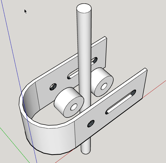
The idea is to use a curved piece of rolled steel stock as a track on which the ends of the chain can run like this:

It’s pretty cheap to build, and seems pretty hearty. I just threw this one together this morning from parts from the hardware store (The bent ring was made by wrapping that piece of steel around the forklift’s propane tank). So far it seems promising, but not 100%. The biggest issue I’m seeing right now is that pulleys I got from the hardware store use a brass wheel inside that rotates around a very loosely fitted pin and under load they seem to want to bind up. Something with real sealed bearings would be a big step forward I think.

I’m going to go see if I can find some better pulleys and do more testing. I wanted to put the idea out there to get feedback and see if everyone can see any ways to improve the idea.

18 Likes

You could pump out a bunch of these on a DiWire right? Or just get buff doing it manually…

You could just cut a plywood arc as well but then you would need a different kind of pulley.

2 Likes

Holy crap. That’s freaking brilliant… And so much simpler than my Ubersled.

Next time you’re at the hardware store you might consider looking at the door hardware. Sliding doors and screen doors use pulleys with better components than the typical rope pulley.

2 Likes

They will cost a bit more than standard hardware store fare, but a sailing block will fit the bill perfectly.

A ‘low priced’ block will usually have a Delrin sheave and roll very well w/o need for lubrication for decades in this situation. (they’re made for corrosive salt environments, any dust can be blown or hosed out easily)

I read that ya’ll were previously up in Port Townsend, plenty of sailors up there, some in PDX too.

2 Likes

:stuck_out_tongue_winking_eye:
Well you just won project of the week!!!

4 Likes

This is the cheapest block i can find that fits the bill: Ronstan Utility Block

I’m sure that that price can be driven down both with research (by $1-2) and likely with quantity.

There are surely other ‘non marine’ options, maybe with better sheave materials, but this block will work very well.

Just curious how you are dealing with the part of the setup requesting the distance between sled mounting points since this distance will be different depending on where the sled is located. From my limited understanding, this measurement is used to compensate for possible rotation of the sled as it moves away from the vertical center of the cutting area. These swiveling sled mounts wouldn’t suffer from rotation in the same way, which it seems would make the math easier on calculating position over the whole cutting area. I am interested to know what the cutting results are.

Thanks for innovating!

To remove all the slop and binding a three wheeled set up could be used. Like how roller coasters hold on to the modern round tracks. Use nylon pulley wheels and standard sealed bearings for skateboards and fidget spinners. You can get them in sets pretty cheap for really high quality bearings thanx to fidgets spinner popularity. kind of like this

Doesn’t have to be that complicated and overbuilt. That’s just the first image that came up when I googled roller coaster wheel assembly. Could just about be 3D printed and use some nylon pulley wheels. Though a metal frame work would greatly increase rigidity…

2 Likes

The portion of the math that requires this measurement is eliminated using this type of a sled. When the bit is always at the point of the triangle (formed by the motors and the sled) that distance is irrelevant.

EDIT: I shouldn’t say it’s irrelevant… in theory the measurement between those points is now a consequence of the angle formed by the vectors (determined by the length of chain fed out at each motor) rather than a variable in the calculation. The radius at which the blocks reside may prove to be a variable worth taking into account… we’ll just have to see. (Sorry… I felt like I was diminishing the research and testing yet to be done with a setup like this)

1 Like

That’s totally reasonable for a block of that quality. I’d prefer a bearing considering the forces involved here but that’s a great place to start.

You could cut the block cheeks with maslow and use a bare bearing on an axle through the cheeks. A pin for the chain connection.

1 Like

Yeah, that’s what I was thinking too. My question is more whether the ground control code would have to be changed to not take that bit of math into consideration, or if the effects would end up being insignificant.
I am now embarrassed to admit that I didn’t notice it was Bar’s topic, so I am sure that he’s got those considerations in mind, as well as having the skills and familiarity with the code to implement any needed changes. That said, I am in the website batch, so I am soaking up all the posts in the time until my unit arrives this fall.

I did do a quick google search to see if I could find a metal bender that would do short runs (I also have another project that needs tube bending that has been nagging me for a while). I don’t know anything about these guys, but if I use their services, I’ll let folks know how they are:

1 Like

its rated to 600lbs, working load, meaning it will spin freely with very little gain in friction, after that (in my experience) the delrin will itself deform or break well before the pin will. The good news is that no matter what, the chances of this happening to a MaslowCNC in the middle of the ocean is still quite low.

I’m sure these can be had for $7-8/ea with a little hustle.

GroundControl is happy with a value of 0.0001mm for the sled width :wink: - not truly zero, but near enough to zero.

1 Like

ah, right! perfect solution.

Just curious how you are dealing with the part of the setup requesting the
distance between sled mounting points since this distance will be different
depending on where the sled is located.

set that distance, as well as the distance from that line to the bit (and
hopefully the distance from there to the CG) to zero. But you need to add the
distance from where the chains actually end to the bit to the calibrated length
of the chains (manual chain length calibration)

Yes, it makes the math much simpler, and if we do much of this, we should add a
test in the math to avoid doing most of it :slight_smile:

GroundControl is happy with a value of 0.0001mm for the sled width :wink: - not truly zero, but near enough to zero.

actually, small values can cause grief. In the simulation, I needed to change
the code last week to make it work with a true zero, when I used a small value,
there were some points where the maslow got confused. a small value makes it
thing that the sled tilts a lot and ‘strange things happen’

1 Like

It seems like enough people are interested in some form of the rotating sled that I want to integrate support for it into GC. There will probably just be a drop down which switches from one to the other

3 Likes

Something like this maybe? Excuse my speed sketchup…

1 Like

It seems like enough people are interested in some form of the rotating sled that I want to integrate support for it into GC. There will probably just be a drop down which switches from one to the other

There are enough variations of this (balanced sled, unbalanced sled, bit
slightly below the center, etc), that we just need to make sure the settings
support l=0 (avoiding the divide by zero). As an enhancement, if l=0 we shoud be
able to skip all the moment calculations as phi = 0 in that case.

1 Like