# Alternate Temp Bracing
**URL:** https://forums.maslowcnc.com/t/alternate-temp-bracing/1090
**Category:** Hardware
**Created:** [November 17, 2017, 1:13am UTC](https://forums.maslowcnc.com/t/alternate-temp-bracing/1090 "2017-11-17T01:13:37Z")
**Posts on this page:** 10
**Page:** 1
### Author:  [@Bee](https://forums.maslowcnc.com/u/Bee)
#### Post date: [November 17, 2017, 1:13am UTC](https://forums.maslowcnc.com/t/alternate-temp-bracing/1090/1 "2017-11-17T01:13:37Z")
lets have a conversation about 2x4’s and fastening systems. For my non US peeps please alter to MM in your head. I’m going to toss a premise out. If anyone wishes to argue or dispute it I will be glad to participate as long as you create a new thread where we can debate it. For the sake of argument we are going ot say a 2 x 4 is resistant to bending more on the edge of the 2 x4 rather that the 4x2 edge due to bias.
One of the figures below shows this -
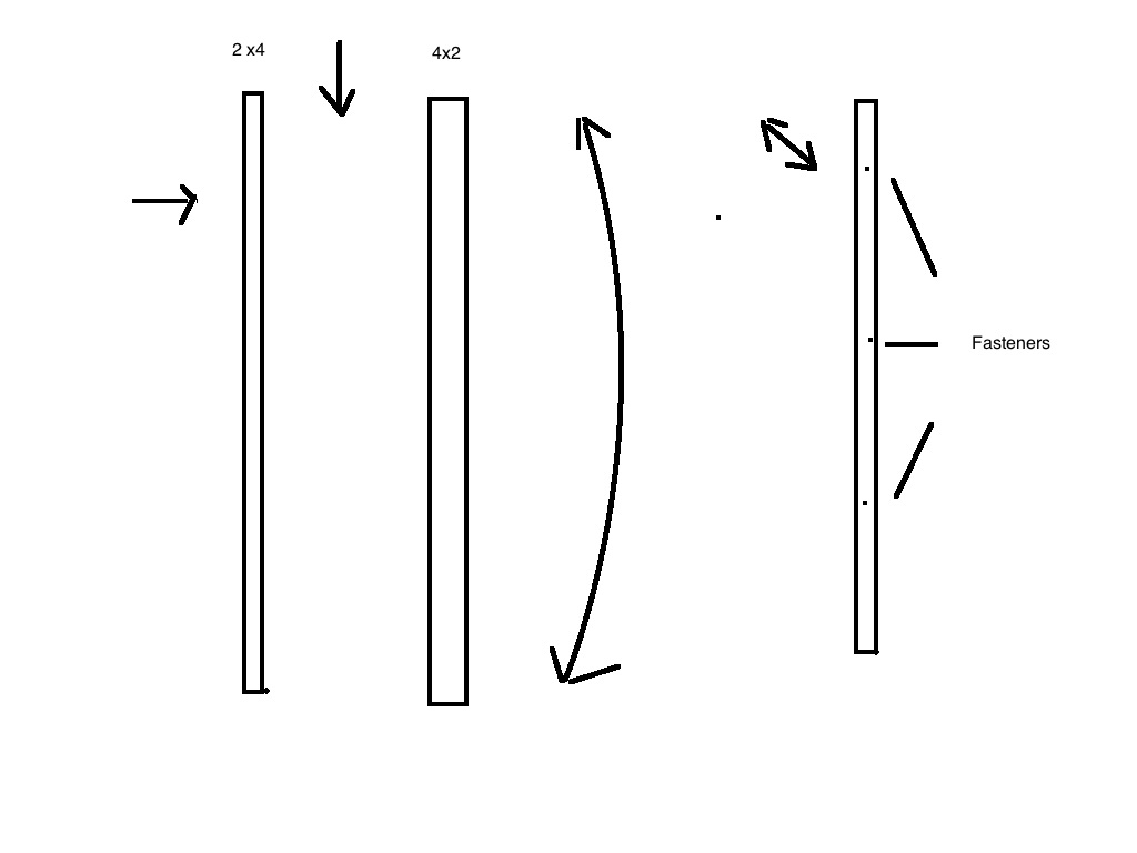
Further when you introduce fasteners you are attempting to crush or expand the material between the fasteners agins it’s shear strength making it avoid flexion more between the points of entry of the fasteners.
Let’s talk about floppy - if you take a playing card and hole it corner to corner diagonally between your thumb and pinky then squeeze, you are simulating the load stress on a 4 x 8 sheet of plywood.
If you tape a toothpick diagonally in the same direction on the card as the force from thumb to pinky it will be much more rigid.
Using this axiom I use the 2 inch side of the 2 x 4 to introduce stiffness. It will require 1 more 2 x 4 x 8ft board.

I started with a saw horse and a concrete block to give it weight to hold the 4 x 8 plywood resting against it. I set the Plywood leaning against the sawhorse and used a 18 inch 2x4 against the plywood against the 4 inch side to keep it from creeping down as I worked on it.
Next I took the 39 & 3/8th boards and marked them at 20 inches and installed them on 45 degree angles as in the standard build. I then user the 53 inch boards at the bottom in place of the 18’s.
I used an 1/8 bit to pre drill my paths then star drive deck screws. Deck screws like this have multiple points of contact so almost never strip, they have a coating to improve driving them and corrosion, they also are self countersinking.
Now to stiffen the build I added a 2 x 4 x 8ft I had laying around on a diagonal from a lower corner to the upper arm. I secured it in 4 points across it’s path with deck screws. Next I used a 57 inch 2 x 4 in the opposite diagonal and again used 4 points across it’s path to foam a Y shape. I thne bridged the top horizontally with the other 57 2 x4 creating a triangle pattern and secured it with 4 fasteners. Last I put the other 18 inch piece in place to secure the new structure for when it was leaning on the sawhorse in the middle.
see the pictures below -


Let me know if you have questions - the purpose was to use as much of the cut parts waiting for the Final frame to make the Temp frame stiffer.
---
### Author:  [@vertex](https://forums.maslowcnc.com/u/vertex)
#### Post date: [November 18, 2017, 7:53pm UTC](https://forums.maslowcnc.com/t/alternate-temp-bracing/1090/2 "2017-11-18T19:53:36Z")
Exellent write-up Bee!
Would be nice if you could add he metric values in braces
1ft (32cm)
12inch (32cm)
This could spare Metric minds a headache or two. 🙂
Whole ft and inches are still doable for most of us ‘metriqueians’ but when something like 39 & 3/8th comes in the picture then it starts to trigger WTF issues. 😃
Still, don’t let that stop you from doing such nice writeups!
---
### Author:  [@Bee](https://forums.maslowcnc.com/u/Bee)
#### Post date: [November 18, 2017, 8:03pm UTC](https://forums.maslowcnc.com/t/alternate-temp-bracing/1090/3 "2017-11-18T20:03:09Z")
Much appreciated and where I can I stop down and add metrics. However I have a person or persons that are just a few hours behind me asking for info. I’m building a 3D printer, Looking for a new job, building and documenting a vending machine project and injecting the Maslow where I can. The plumbing in the house blew out the other day too. So SNAFU - lol. I will be putting together a small book on my entire build once I’m done.
---
### Author:  [@vertex](https://forums.maslowcnc.com/u/vertex)
#### Post date: [November 18, 2017, 8:51pm UTC](https://forums.maslowcnc.com/t/alternate-temp-bracing/1090/4 "2017-11-18T20:51:20Z")
I’m not sure if this forum allows to, but it would be nice if certain top posts like this could be edited by others then the original writer (with permission of course)
This way we eventually could work together on making write ups, and once ready then move them to the wiki as a final publication.
No worries though, better to first get that plumbing fixed.
Thanks for the invested time to provide a view in your garage. 🙂
---
### Author:  [@Bee](https://forums.maslowcnc.com/u/Bee)
#### Post date: [November 18, 2017, 9:02pm UTC](https://forums.maslowcnc.com/t/alternate-temp-bracing/1090/5 "2017-11-18T21:02:57Z")
It should be roughed in and moved to the wiki. You are encouraged to copy it and add it there. 🙂
---
### Author:  [@vertex](https://forums.maslowcnc.com/u/vertex)
#### Post date: [November 18, 2017, 11:06pm UTC](https://forums.maslowcnc.com/t/alternate-temp-bracing/1090/6 "2017-11-18T23:06:19Z")
Great idea, let’s give it a go
> [@Bee](#):
>
> lets have a conversation about 2x4’s (5x10 cm) and fastening systems. For my non US peeps please alter to MM in your head. I’m going to toss a premise out. If anyone wishes to argue or dispute it I will be glad to participate as long as you create a new thread where we can debate it. For the sake of argument we are going ot say a 2x4 (5x10 cm) is resistant to bending more on the edge of the 2x4 (5x10 cm) rather that the 4x2 (10x5 cm) edge due to bias.
>
> One of the figures below shows this -
>
> 2by4.jpg1024x768 24.7 KB
>
> Further when you introduce fasteners you are attempting to crush or expand the material between the fasteners agins it’s shear strength making it avoid flexion more between the points of entry of the fasteners.
>
> Let’s talk about floppy - if you take a playing card and hole it corner to corner diagonally between your thumb and pinky then squeeze, you are simulating the load stress on a 4’x8’ (122x245cm) sheet of plywood.
>
> If you tape a toothpick diagonally in the same direction on the card as the force from thumb to pinky it will be much more rigid.
>
> Using this axiom I use the 2 inch (5cm) side of the 2x4 (5x10 cm) to introduce stiffness. It will require 1 more 2 x 4 x 8ft board. … **uhm… this one is a bit unclear**
>
> brace 1.jpg1024x768 57.7 KB
>
> I started with a saw horse and a concrete block to give it weight to hold the 4’x8’ (122x245 cm) plywood resting against it. I set the Plywood leaning against the sawhorse and used a 18 inch (46cm) 2x4 against the plywood against the 4 inch (10cm) side to keep it from creeping down as I worked on it.
>
> Next I took the 39 & 3/8th (… **thisone I don’t compute myself** \*) boards and marked them at 20 inches (51 cm) and installed them on 45 degree angles as in the standard build. I then user the 53 inch (135 cm) boards at the bottom in place of the 18’s. (46cm)
>
> I used an 1/8 bit ( **…this is 6mm?** ) to pre drill my paths then star drive deck screws. Deck screws like this have multiple points of contact so almost never strip, they have a coating to improve driving them and corrosion, they also are self countersinking.
>
> Now to stiffen the build I added a 2 x 4 x 8ft ( **…thatone again** ) I had laying around on a diagonal from a lower corner to the upper arm. I secured it in 4 points across it’s path with deck screws. Next I used a 57 inch (145cm) 2 x 4 in the opposite diagonal and again used 4 points across it’s path to foam a Y shape. I thne bridged the top horizontally with the other 57 (145cm) 2x4 (5x10 cm)creating a triangle pattern and secured it with 4 fasteners. Last I put the other 18 inch piece in place to secure the new structure for when it was leaning on the sawhorse in the middle.
>
> see the pictures below -
>
> Let me know if you have questions - the purpose was to use as much of the cut parts waiting for the Final frame to make the Temp frame stiffer.
That’s about it. The few sizes i couldn’t convert without being sure of being correct, those I made \*\* **bold** \*\*
---
### Author:  [@rovino](https://forums.maslowcnc.com/u/rovino)
#### Post date: [November 22, 2017, 4:25pm UTC](https://forums.maslowcnc.com/t/alternate-temp-bracing/1090/7 "2017-11-22T16:25:32Z")
Hi Bee
Thank you for this write up. 2 questions.
1st one seems obvious just wanted to confirm when you attached the 2x4 “Y” sections to the plywood did you screw them from the plywood side?
2nd questions… I uploaded your image and circled the 4x2 piece of wood attached to the short arm of the “Y” section. What is that piece for? seems un-needed. 
---
### Author:  [@Bee](https://forums.maslowcnc.com/u/Bee)
#### Post date: [November 22, 2017, 5:44pm UTC](https://forums.maslowcnc.com/t/alternate-temp-bracing/1090/8 "2017-11-22T17:44:27Z")
I did use deck screws from the plywood side. The small piece is to keep the entire frame from moving when it’s sitting up against the top of the saw horse.
Thank you
---
### Author:  [@Onelonedork](https://forums.maslowcnc.com/u/Onelonedork)
#### Post date: [November 24, 2017, 5:17pm UTC](https://forums.maslowcnc.com/t/alternate-temp-bracing/1090/9 "2017-11-24T17:17:19Z")
 
Inspired by your design, I braced the A-frames for even spacing. After that, I framed in the arms and braced it with an attachment to a frame. 3 inch deck screws were used for everything.
---
### Author:  [@Bee](https://forums.maslowcnc.com/u/Bee)
#### Post date: [December 14, 2017, 9:21am UTC](https://forums.maslowcnc.com/t/alternate-temp-bracing/1090/10 "2017-12-14T09:21:54Z")
OK - this is added to the Wiki now -
> **[MaslowCNC/Mechanics](https://github.com/MaslowCNC/Mechanics/wiki/Alternate-Temp-Frame)**
>
> Digital Design Files. Contribute to MaslowCNC/Mechanics development by creating an account on GitHub.
Thank you