In search of accurate measurements

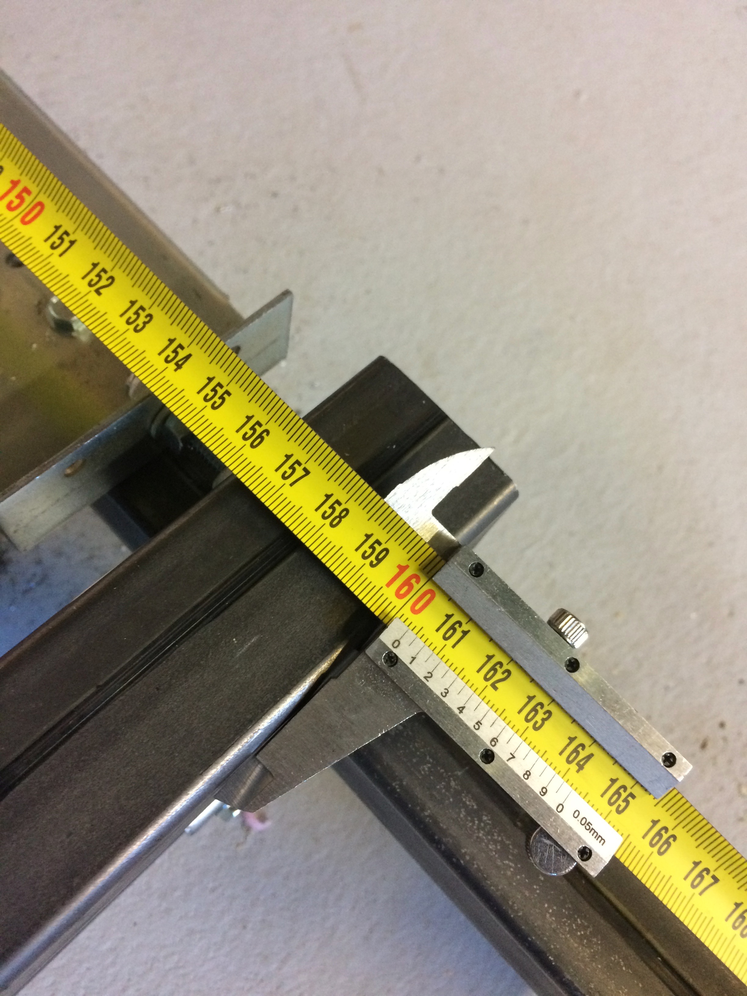
at one point, someone posted a picture of a caliper setup that they had which used a tape measure that let you measure down to 1/10 mm over whatever length tape measure you have.

I have created an item in onshape with the idea of 3D printing two of them, one to go on the end of a tape measure (any tape measure up to ~1" wide), and the other to be used for the measurement. These have pins to work with the holey triangulation calibration holes.

However, my experience with 3d printing is limited, Iā€™ve done a few things, but nothing requiring significant accuracy. I think I know enough to ask most of the questions to make it work, but I donā€™t know the answers. I could really use someone with good 3D printing/design experience to look over the design and help me figure out how to make sure that this is actually printable :slight_smile:

there are two parts, the second would be flipped upside down to print it.

there is a bit of overhang on the pin, but I cut it off where the curve of the pin hits 45 degrees (we could go a little more and then shave the pin to make it round I guess, but I think this is pretty close and probably good enough)

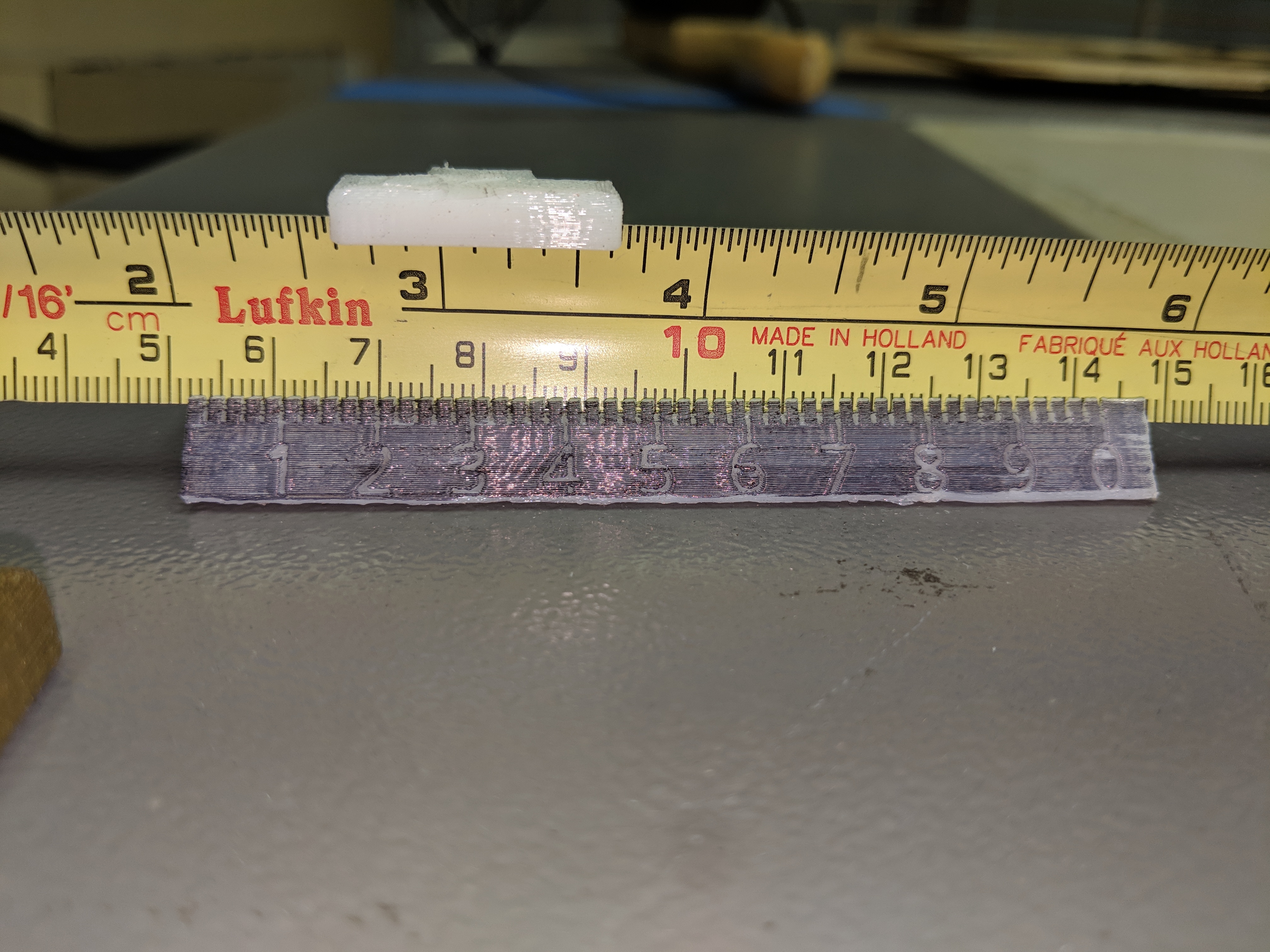
the numbers will have some overhang, I could make the numbers recessed, but the marks above them would end up with the edge having notches, so I figured they are better standing proud.

This has no allowance for the fact that the 3D printer extrudes on both sides of the line (can this be handled in the slicer?)

There is no allowance for part shrinkage (can this be handled in the slicer?)

Itā€™s very possible that I have specified things too tightly.

the onshape link is at Onshape anyone can view it and Iā€™ll grant edit rights to anyone who wants to tinker with it.

edit: the original link points to a tab on the document that no longer exists (it still works, but gives an error message), here is the updated link. Onshape

3 Likes

I donā€™t have anything to keep the dovetailed holder in place yet, and Iā€™m
wondering if I should ditch it and instead just have a couple of magnets
somewhere.

I suspect that I have features that are just too small for practical
printing/use, but until someone tries to print and use it, I donā€™t know any
better :slight_smile:

David Lang

2 Likes

I think it is a really good idea!

I donā€™t have any 3D printing experience, so I canā€™t comment on that.

Just going to throw out some ideas/thoughts. Maybe good, maybe not.

  • The holes that we drill are typically very shallow.
    • Should we drill deeper holes, so this has a significant hole, to push into?
    • Should there be something which helps to tape this thing to the surface, so it doesnā€™t move once in-place?
  • Are the marks spaced to enable a verneer-type measurement?

Just going to throw out some ideas/thoughts. Maybe good, maybe not.

  • The holes that we drill are typically very shallow.
    • Should we drill deeper holes, so this has a significant hole, to push into?

with a deep enough hole this could be a one-man operation.

I found that trying to do this on foam didnā€™t work very well, I can feel the
hole, but barely see it, and it sure wonā€™t hold anything (but it should work as
a two-man measuing job)

  • Should there be something which helps to tape this thing to the surface, so it doesnā€™t move once in-place?

I donā€™t think so, we either need this to pivot, or itā€™s a two-man job.

  • Are the marks spaced to enable a verneer-type measurement?

Yes!!, thatā€™s how we can get to 0.1mm accuracy in the measurement.

when printing, you can use these to check that the hook/measuring edge is in
exactly the right and sand the printed piece as needed to get it to match
exactly.

David Lang

1 Like

It seems like some kind of set-screw would be valuable, to hold the tape in-place.

thatā€™s what the dovetailed piece is for, to hold the other edge of the tape. I
really should have put a slot and screw of some sort to hold that in place.

as I posted it, I had the thought that it may make sense to put in a magnet to
hold the tape. The problem with this is that different tape widths would want
the magnet in different places (and I assume have different curves to them. That
was why I took the approach of clamping from both edges of the tape.

Iā€™m open to other suggestions.

David Lang

Just printed it. Used Cura, 0.1mm per layer , speed 40mm/s.

  • The dovetail doesnā€™t fit (printed at 100%)
  • The lines above the numbers are not printed.
  • The numbers do not match the metric system (correct?). Every number is approximately 9mm apart.
  • Black is not the ideal color :sweat_smile:

that actually looks pretty good.

I expected the dovetail to not fit as I donā€™t give it any clearance. I donā€™t know what I would need to give. can you sand the sides to make it fit?

I just did a second version with the numbers and lines as indentations rather than being proud (and am just finishing up test blocks to see how thin a line we can make it)

I am figuring out the right spacing for the lines, the intent is to be a vernier scale, just slightly smaller than 1cm between numbers so that you can line up the lines with the lines on the tape measure to read it to sub mm accuracy https://en.wikipedia.org/wiki/Vernier_scale

with the lines 0.9cm apart, this lets you read to 1mm accuracy (which you already have), so right idea, wrong implementation on this version. Iā€™m working to figure out what I should have done now.

could you print one or both of the gap test and line items so we can see how thin a line we can make?

also, how close is the pin to being 1/4" diameter?

David Lang

I tweaked the design quite a bit and this is looking pretty good

I fixed the spacing of the marks while this was printing and did a few other tweaks to speed up the print and slim it down a bit.

This was using a sharpie tocolor the surface so the numbers and slots are more visible. I think that printing in dark filament and then putting a drop of white paint in the numbers and lower portions of the slots would be ideal.

This looks like it can give us 0.02mm accuracy, past the point where the exact fit of the peg in the hole is the limiting factor. The cheap digital calipers claim an accuracy of 0.01mm, so we arenā€™t really going to get 0.02mm with this, but I donā€™t know how close we can really get.

This is very sensitive to the filament and printer settings. I did two prints, the first was almost impossible to read and the dovetail could fit, but it didnā€™t move freely, the second is easier to read and the dovetail is very sloppy. With the first, the 6.25mm pin measured 6.68mm, with the second the 6.05mm pin measured 6.08mm. the model needs to be tweaked if you get the wrong pin diameter, do NOT scale the model

I also made a 0.05mm version thatā€™s a little smaller and may be easier to read

1 Like

Just printed it (again) :slightly_smiling_face:. Same settings in Cura.


Printing time decreased and the line/spaces come out nice this time.
Is it correct that the scale isnā€™t a Vernier-scale anymore? The ā€œzeroā€ spacing at the end matches the 10 cm exactly. Or am I missing something? As a financial analyst Iā€™m more of a debit/credit kinda guy.

I if simply mirror the STL-file, can I use that part for the other end of the tape measure?

itā€™s still a vernier scale, it just starts 1mm to the right so that the 0 lines up at a cm line instead of 1mm early.

you can use the same part on both ends.

on the end of the tape (as you show), you can check exactly how close to accurate the moving piece is, read the vernier and that is the error on the end of the tape

then use the exact same part at the other measuring point and read the distance, adjust by the error at the start.

you may want a rubber band around the moving part (or just a layer of tape in the dovetail) to keep it snug. I used a set of the 0.05mm ones last night and they worked well. Iā€™m waiting for a print of a pair of 0.02mm ones right now (my printer doesnā€™t have the resolution to print the 0.01mm ones)

Help me understand.

I see 5 lines between the 1 and 2 mark, including the 1 mark. If I count the edges, 2 per line, I count 9, and the 10th would be the next mark. Based on that counting, it is not a vernier scale.

It looks like the 1 mark lines up with 11 mm; the 2 mark lines up with the 21 mm, the 3 mark lines up with the 31 mm, etc.

I must be mis-interpreting this.

I think you are trying to read it as if the parts that stick up are the markers,
when itā€™s the gaps between them that are the markers (you look for the line on
the tape measure in the slot)

there are several configurations available now

in every case, the ā€˜0ā€™ mark is not shown on the left side and would be centered
exactly 1mm from the end.

0.01mm has small ticks every .99mm and large ticks (and numbers) every 9.9mm, so
when you add the 1mm offset, the last gap should line up with the 10cm (100mm)
mark.

0.02mm has small ticks every 1.98mm and large ticks (and numbers) every 9.9mm,
so the same total distance as the 0.01mm version, just with larger spaces
between the lines

0.05mm has small ticks every 2.95mm with large ticks every 5.9mm (with the final
gap at the 6cm mark on your tape)

0.05mm tight has small ticks every 1.95mm and alrge ticks every 3.9mm, it lines
up with 4cm at the end, but the numbers may blur together (depending on your
printer)

0.1mm has small ticks every 1.9mm and no large ticks or numbers

0.1mm wide has large ticks every 3.9mm with numbers

and there is a 3dtest version that doesnā€™t print to full height and has spacing
between the gaps of 1,2,2,1,3,3,1,2,2,1 mm. Itā€™s designed to let you quickly
print something out that you can tweak settings with to see how tight a
resolution you can get and to tweak the dovetail to fit nicely and the pin to be
exactly 6.35mm diameter

David Lang

1 Like

Good work guys, this looks like a great little tool. Do you feel like it is ready for community use or are you still tweaking things? I donā€™t have a 3D printer and would be interested in purchasing from someone.

2 Likes

Iā€™m pretty happy with it, I think itā€™s ready for wide testing at least.

For my eyes (and available 3d printer), I am thinking that the 0.05mm version is
about the sweet spot of accuracy vs ease of use. Iā€™d really like to have some
other people try it.

I havenā€™t yet investigated what it takes to post a design on thingiverse,
especially one with multiple options/configs available. I know Iā€™ve seen people
do it, but havenā€™t looked at what it takes.

There are various services that let you upload .stl files and they will print
them for you, I would suggest contacting some of them and sending them a link to
the onshape document, asking them about details like how accurately a part
thatā€™s in the model at 1/4" actually translates to 1/4" in the real world.

On my printer, simply changing the filiment with no other changes resulted is
differences in that 1/4" feature size that were significant. I created the3D
test version to have something that would print much faster (15-30 min vs
several hours on my printer) and let you check your machineā€™s results.

David Lang

2 Likes

The link in your first post is the latest / greatest?

This is what inspired this project. If anyone knows where to buy one of these, please let me know.

Here is an image of the .02mm version. This shows that the end of the tape is short by .42mm (itā€™s showing the line matching the slot at .58mm, but if you look at the 0 at the end, you will see that itā€™s past the 10cm mark, so ā€˜0ā€™ on the tape is actually .58mm past the 1mm mark on the tape

This is a 0.1mm version showing the pin at 209.9mm

This is the 0.05mm version showing the pin at 131mm (we donā€™t quite have the right camera angle, but it looks like the line matches at the ā€˜0ā€™ mark)

This also shows the test piece in the forground, it shows the pin spacing needed for various versions and is fast to print so that you can fine-tune the pin diameter/length, the dovetail fit, and the width of the lines.
There is a very short pin to the left of the 1, to the right of the 5, if they work well, you can print the 0.01mm version, if you have good pins between the 1 and 2 you can print the 0.02mm version, if they donā€™t work, you have the pins to either side of the 3 and have to stick with the 0.05mm or 0.1mm versions

1 Like

it still gets you to the document, but gives you an error since the tab no
longer lists. Here is the updated link

https://cad.onshape.com/documents/6ad35fdba3e3babde64e604a/w/a26beded4d7ab9aea561ab08/e/98faa5467fe149a4529f83e0

at the very top left there is the vernier accuracy configuration that will let
you select the version to use.

you need to clone the document to be able to set the variables for tuning the
pin, lines, and dovetail.

David Lang

2 Likes

That looks like the back end of a standard vernier caliper with the front removed thatā€™s been slid over a tape measure.
we could probably use something like this, itā€™s not going to be as accurate as a starrett, or other high quality caliper, but as our primary scale is a tape measure, it probably doesnā€™t matter, provided the tape measure can be made to fit snugly in the slot.