The frame design has remained largely the same while the other parts of the machine have steadily improved. The community has made a number of different frame designs each with their own strengths and weaknesses. It’s time that we collected the improvements the community has made and re-designed the stock frame.
The goals are:
Simple to construct
Uses low cost universally available materials
Provides increased rigidity from the original design
Let’s talk about features we like and designs elements that we can add to the stock frame design!
I think that the top bar frames are a clear winner. I also have heard several people mention that they have seen improved chain feeding by moving the attachment point for the bungie’s forwards several inches so I think that we can redesign the lower arms also.
One question I have is on the topic of frame flex. The stock frame seems to have the 2x4 (or similar sized piece of wood) with the short dimension facing forward. In the case of a 2x4, that means the depth of the motor mount is 2 (1.5) inches. A 2x4 is prone to bending easily in that dimension, and I am wondering if another 2x4 connecting the motor arms would be effective at stopping that.
I would suggest at least three vertical members, at the middle and ends of the workarea. They would stiffen the “motor bar” against warp and twist, stiffen the workarea sheet against curl, and stiffen the frame against parallelogram distortion.
I agree that we want a 2x4 running directly between the motors. As for which direction it should face I am a little less clear. It seems to me like the force vectors are along the chains which is almost 45 degrees to the direction of the board making the force (at least in my mind) even in both the inwards and downwards directions.
Another question I have is how to push the top bar inwards the 10cm or so to place the motors in line with where we want the chains. How have other top bar frames done this?
These depend on how far the the motor sprockets are from the centerline of the beam. With the present motor mounts, there is a lever arm several inches long that works to bow the beam in the horizontal plane.
Yes – We joined 2 pcs. together at 90 degrees to make an L-shaped cross section to resist flexing in both planes – Because we’re a woodworking shop, we had rippings of clear dry hardwood to use – Construction lumber might be prone to warp and twist as it dries – Perhaps use 4" x 8’ rips of 3/4 ply – one plane using 2 - 8’ pcs glued end to end (maybe with a short pc. spanning the joint for re-inforcement, and the other plane with a 4’ pc. each end with an 8’ in the middle, to stagger the seams – Strong, light, and stable – We used a similar assembly for a cross piece supportinga the top edge of the 4x8 work sheet – The flat horizontal board also makes a nice shelf to put the cotter pins on when you’re measuring the chain lengths!
Flex
The ‘wing’ frame gives the motors a lot of leverage (it puts the motors several inches out from the arms, and the arms 18 inches above the plywood, and it’s the plywood and all the screws that need to resist flexing)
You want to give the chains/motors as small a lever arm as possible against the pull of the chains towards each other.
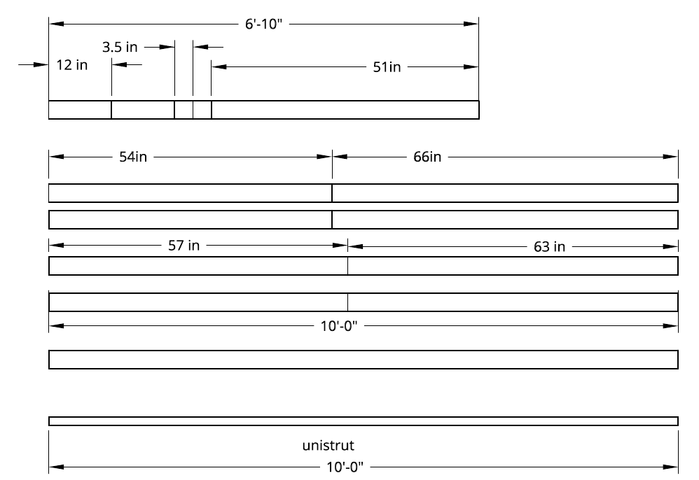
Ideally, you do this by mounting the bracket so that it’s flush with the front of a solid beam (wood or unistrut) that connects the motors (unistrut is not quite as common as 2x, but it’s not far behind, I think the design should support both)
Chain positioning
The ‘wing’ frame forces you to compromise between the chain being parallel to the workpiece, and it being at the balance point of the sled. The stock motor mounts put it at a reasonable place for working on 1/4"-1" material, but beyond that (including thick waste boards), you want to move the motors out.
It would be good to eliminate the wood motor mounts entirely and mount the metal motor mounts directly to the top beam. This requires having some ability to move the beam out from the back. Making this adjustable is pretty easy once you have it out at all.
Plywood quality
The ‘wing’ frame uses the plywood as a structural element. The ‘top beam’ approach eliminates most of the stress, but you still have the legs attaching to the plywood. With just a little framing, the plywood can cease to be a structural element. I can be the wasteboard directly, or at least be shrunk down to a 1/2 cheap plywood
I posted a new idea for the chain takeup a couple days ago chain take up idea
This takes the idea of the plywood chain guide (two layers of plywood where the chain rides against the back of one and the side of the other) and extends it to take up the chain, not just passively guide it
I posted a new shape for the metal motor mount brackets a couple days ago new motor mount suggestion This has holes to mount it to wood or unistrut, and has a tab to keep it from sliding down the beam.
It also replaces the slots with holes so it’s less likely to twist (although, especially for unistrut, it depends on the back and end flaps to keep it from twisting more than the screws/bolts)
I saw that and it looks really cool! Unfortunately we had to put in the order for the motor mounts quite a while back to get them on time so we can’t change them for this version
This is how I built my frame actually, so that the front plywood is not structural. I haven’t put my front plywood piece on yet because my kit is still coming, so I could snap some pics too.
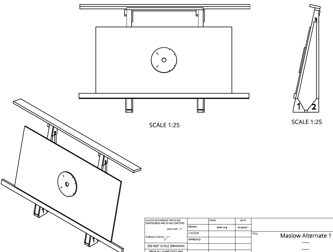
I have been working on a folding design for a while, and earlier on did an A-frame top-beam design. The A-frame design doesn’t have all the refinements of the folding one.
The A-frame design enlarges the A-frames from the stock maslow and still uses the plywood as structure.
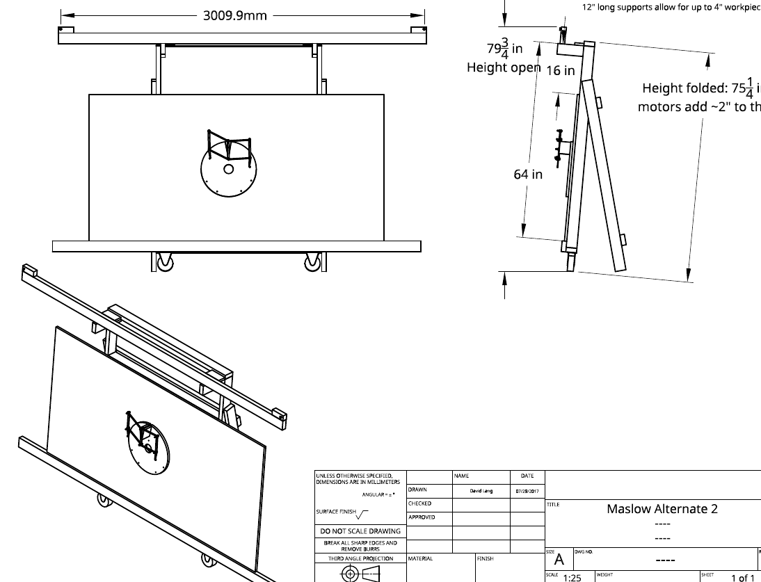
The folding version I like a lot more, it’s built almost entirely out of 2x4s (with one potentially being a piece of unistrut) and the only thing it uses plywood for is the sled and brick mounts
For the folding version, I put wheels under it so that when it’s folded, I can wheel it into the garage on edge. It would be pretty trivial to add fixed legs and fixed braces to convert it from a mobile design to one that’s fixed. There’s enough wood left in the last 2x4 to do this sort of thing