Lowe’s/Home Depot have tons of “Builders hardware”. Braces, angles, etc. It seems like one could be found that would add a lot of rigidity to that joint for under $5 per build. I could look for something if it seems like a workable solution.
1 Like
i think that this connection at #3 is going to be problematic.
the lever arm with such a small (distance between connection points)
will likely be too much of a cantilever with the weight.
Let’s move on from issue #3 for a minute and talk about issues #1 and #2
I’ve built my frame as a drew it in the CAD model and I think we can do better on the lower bracing.


What are everyone’s ideas on how to do the lower arms that the bungee’s attach to? Is there a way to do it which also adds support to the plywood without causing an obstacle for the sled?
1 Like
Can a chain guide be built that keeps the slack part of the chain at the sprocket in line with the tensioned part of the chain yet allow it to ‘flex’ back to the back beam?
1 Like
I can’t really draw this right now, but my son has an art desk that can be adjusted to different angles, and at the bottom is a metal tray to hold the work piece when the table is upright. The metal tray has two slots cut into it so that when the table is adjusted to the flat position, you can loosen the screws and slide the tray back out of the way. Seems like some thing similar could be done here with a strip of 3/4" plywood and some wing nuts. The depth could be adjust so that it’s slightly below the workpiece.
1 Like
Will @MeticulousMaynard beautiful chain guide solve the problem with chain skips? That’s why we wanted the put the bungee mounting point in line with the chain/sled/etc… correct?
Yes, this does align the slack chain with the back-side of the motors. I was having a lot of trouble with keeping enough tension on the slack side of the chain keep it from jumping at the sprocket. This entirely fixed the issue. I’d still like to use a chain take-up system like @dlang has suggested to keep better tension on the chain. The added bonus is that the spool could be located above the worksurface, so you don’t need to run the chain to the fence/bottom beam.
It does, however, add a CNC’ed part to the cut list and from what I understand we’re trying to avoid that as much as possible with the new frame. Could easily be a gen 1 upgrade though, as you don’t need the machine tolerances to be incredibly tight for them to work.
Maybe add a couple pieces of precut plywood to the kit. It doesn’t have to be adjustable. I think you just need one piece that’s round and one piece that just larger than the round piece. Could be bolted or screwed  to the top beam below the motor mount.
Mine can be swiveled to change it’s location in the z-direction, but I don’t anticipate the need to change it
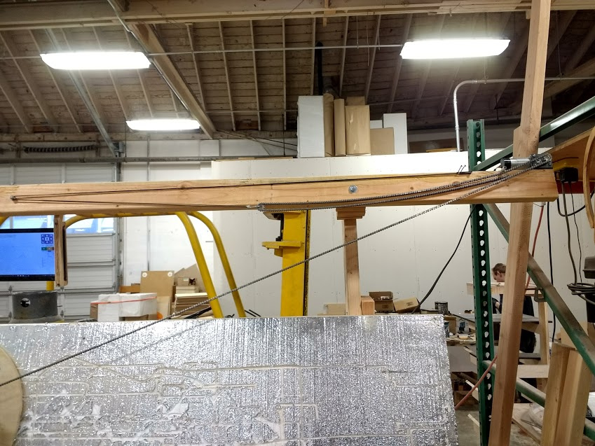
Here’s an outside the box idea…what if we don’t need lower arms?
We’ve got this beautiful new beam across the top, what if we used it instead? It keeps everything in plane and I think it’s tidier.
A setting will be needed to make it work, and I think I can shuffle the routing of all the lines around to clean it up a little, but the first attempt seems promising:

8 Likes
One thing that I can add to this question is that @mrfugu’s idea of putting the chain roller into the threaded hole of the motor means that the chain cannot come off of the sprocket to skip. I also put standoffs to move the bungie pulley at the base of the frame out to the same xy plane in the z direction as the sprocket and I have not had any issues with skipping at all. in fact, whenever I recalibrate the chains, I have to remove the roller otherwise I can’t get the chain off of the sprocket. If the roller can be implemented in this way on the stock frame, then no additional parts would need to be added.
If we can run the slack chain horizontally, that is a beautiful solution.
We can then have a crossbar even with the legs and flush with bottom of the workpiece we can have fixes/removable/sliding/rotating tabs to support the workpiece/wasteboard
2 Likes
Interesting idea! Does that require a rewrite of how the motors move? Will that then result in an option in GC to indicate which orientation the chains are wrapped on the sprockets?
I am a little partial to the current design because 1) I’ve already got it together ![]() and more importantly 2) I am interested in trying the bungie counter balance system that @Brr devised.
and more importantly 2) I am interested in trying the bungie counter balance system that @Brr devised.
That said, it is a very elegant solution
I had been wondering something similar to @gthiesfeld 's suggestion. An adjustable bottom lip extended a little forward or backward, depending on thickness of backer boards and project wood.
So the chain comes off the outside bottom of the sprocket instead of the top inside?
That will change the math
I thonk it’s worth it
3 Likes
i don’t see any reason this can’t be done on the old ‘winged’ frame. The slack is in the air between the wings
1 Like
I like it, the lower wings are often in the way.
I think it could be improved by replacing the ‘stretchy string’ with a cord and a weight using the other two sheaves to lead the cord back to beneath the motor so the weight would hang below that.
2 Likes
Even better, the weight provides constant force rather than less force when there is more weight of chain to control
4 Likes
Could the counterweights fall from the center of the top beam behind the Maslow? I don’t know if the angles work out, but it would be less cord to run.
2 Likes