Chapter 2 General Setup Information
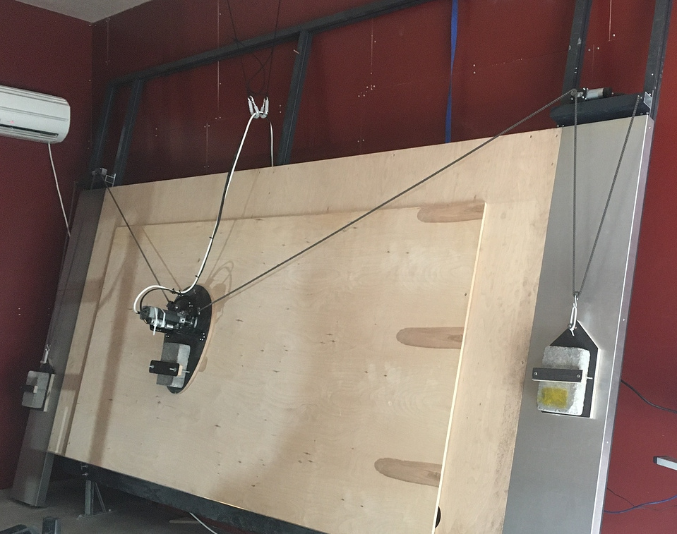
Congratulations, on getting your Maslow. Now that you have committed to this project, be aware there are some design choices that should be considered when building a frame. The frame build instructions are simple. The “standard frame” has a 10’ beam with a Y axis height of 18". The desired work piece slope is 15 ° from vertical. When building the frame, the system will function +/- 5 ° of this.
Many have built oversized frames to get more precision in the lower corners to be able to cut complete 4’x8’ sheets. One common oversize frame has the beam at 12’ with the motor Y offset at 30" (see diagram below). This oversize frame requires 15’ chains instead of the standard 11’ chains. The 12’ beam width gives more side force in the lower corners to allow the sled to cut towards the left or right side into the corner. The higher beam lowers the force on the sled in the upper center region to prevent too high of force on the chains.

If too steep (< 10°), then the router sled will tend to tilt away - the top will pull back from the work surface making a shallower cut- when it is near the top center of the work area when the chains are pulling at the sled from the sides. If the frame angle is too high of an angle (> 20 °) then the sled weight contributes more to friction and impedes the sled movement often resulting in irregular cuts in the lower corners because it sticks (diagram here).
Below are a number of pictures of maslow sleds shared by various users on the forum. To summarize: the rigid router base on the sled was the default purchase option until early 2020 when the metal sled with the linear bearing z axis and the maker made m2 sled came out. Sleds are typically a wooden slab or possibly a metal plate with a ring or linkage connecting to the chains. the sled holds the router and the vacuum connection hose to remove cutting chips. Of critical interest is the Z axis configuration and there are many different designs typically in how the router is mounted to the moving slides and what materials are used for them. With a standard rigid router base lead screw moving 3.17 mm per revolution of the shaft, upgrading to a linear bearing bumps this up to 8 mm/revolution and with a belt and various gearing, that can be doubled or tripled as well. In the end, the more robust the z axis design, the more consistent the depth of cut.
Sled considerations
Most use wood (makermade or eastbay),

some use metal (metalmaslow.com),

some put plasic for lower friction and still others totally customize their sled.

this is a second generation (M2) sled available from makermade.
Understanding the center of gravity of the sled will help with proper ring height adjustment and weight selection for maximizing cut area and minimizing sled tilting or pulling away from the work area. For consistent cuts, the router sled surface must remain in close contact to the work piece / sloped frame surface. Forces that pull the sled in a tipping motion will disrupt the bit penetration angle and cause irregular cuts. Set the ring height based on the “hanging test.” Then set the motor distance from the work piece for the ring height so the chains are equidistant from the work piece between the motors and the router and don’t pull the router away or into the work piece (diagram here). When assembling your sled, please be aware of ring height, total weight, smooth z-axis motion, absolutely centering the ring and the router and how that router z axis motion will allow dust collection.
Much time, effort, and angst has been expended on the z axis of the sled. There are several options including
a metal c-channel,

the metal gantry
the beefy z,

a wooden “meticulous” option,

a 3D printed option,

and the
standard z-axis for the rigid router.

Attaching the router to the z-axis movement can be accomplished with a 3D printed clamp option, a metal clasp, or a wood clamp mechanism for either a c channel or a meticulous axis.
the BLING router setup:
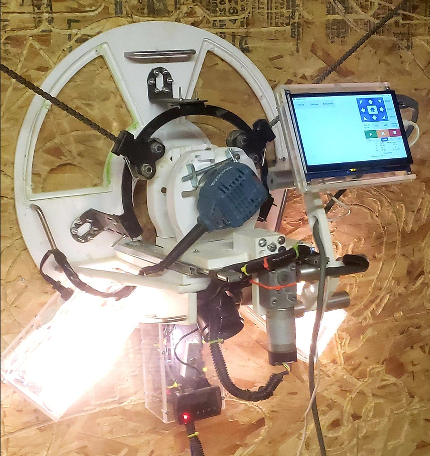
For routers other than the rigid, the standard z-axis may not be recommended. With the rigid router, don’t forget the [bungee] to keep the position compressed down to maintain consistent height whether moving up or down (Z-Axis Bungee To Ensure Correct Depth).

If you experience issues with your standard Z-axis, please be sure the clamping mechanism is closed, but not tight to prevent movement. Some suggest and use dry lube on the router body to help avoid binding during z-axis movement. If your movement arm is having trouble with too much slop, please check here for options to repair or improve its function.
##Dust Collection
A dust collection / vacuuming can be a great help in maintaining a clean safe work area. There are several approaches. If a channel is cut in on the bottom of the sled, that channel can serve as a suction cup to make moving the sled very difficult. Any rough edges on the bottom of the sled should be rounded or at least chamfered to prevent the sled from catching on uneven cut surfaces. Many of the options offer a 3D printed vacuum hose attachment option for dust removal.
##Installing Electronics on the Frame
Assembling the electronics is simply plugging in the cables. Plug them in all the way. Plug the power into the shield, NOT the arduino plug shown correctly unused in the photo below
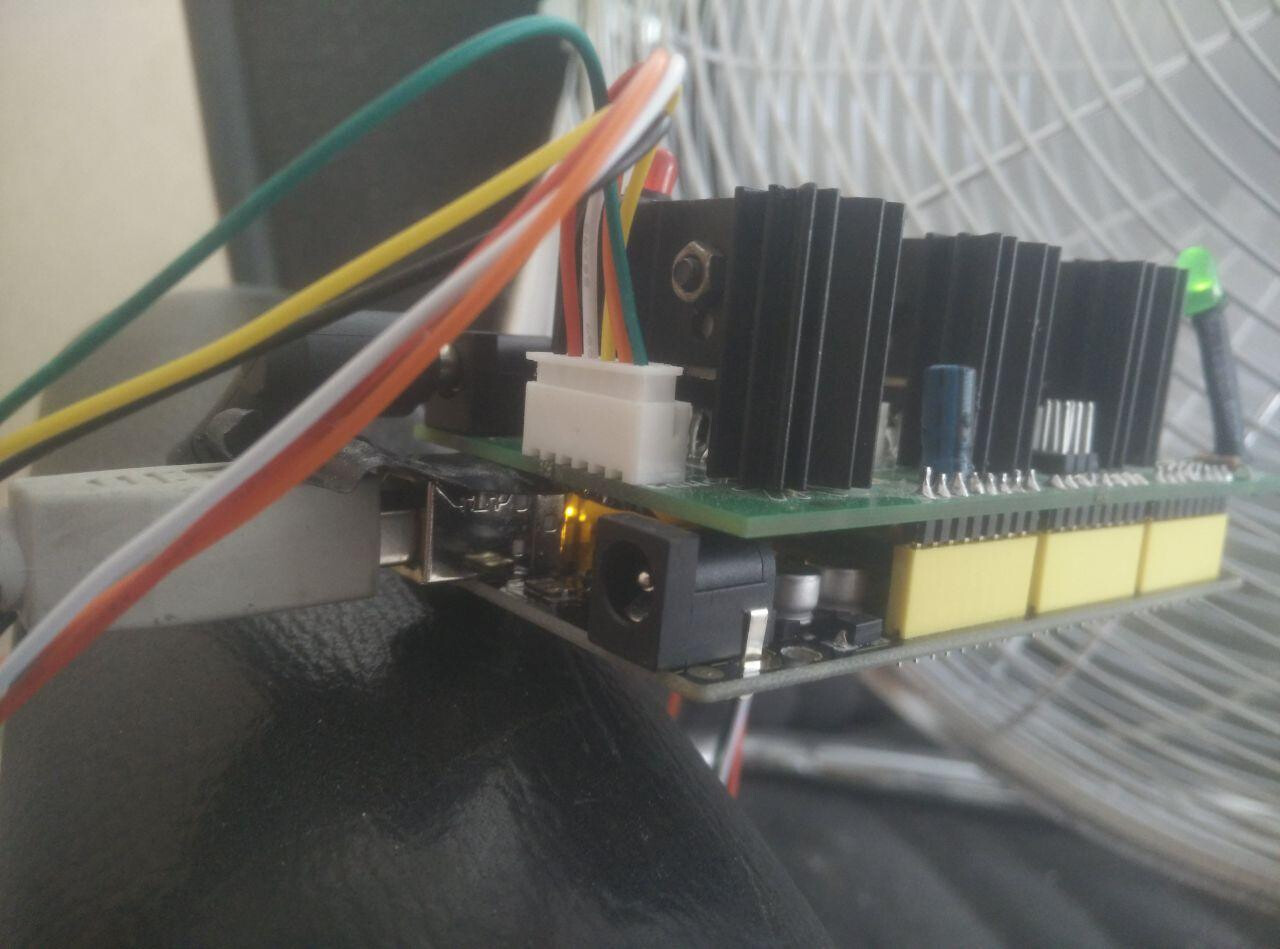
Use a USB cable shorter than 6’ for best signal. route your router power cord away from your z-axis wire.
Please consider how to mechanically connect cabling so the connections don’t pull loose as the sled moves or the system vibrates with use. Attaching an eyelet with a zip tie to anchor cabling helps to secure connections. Many users initially have issues with motors that are solved in many cases by plugging in the cables that have worked loose.
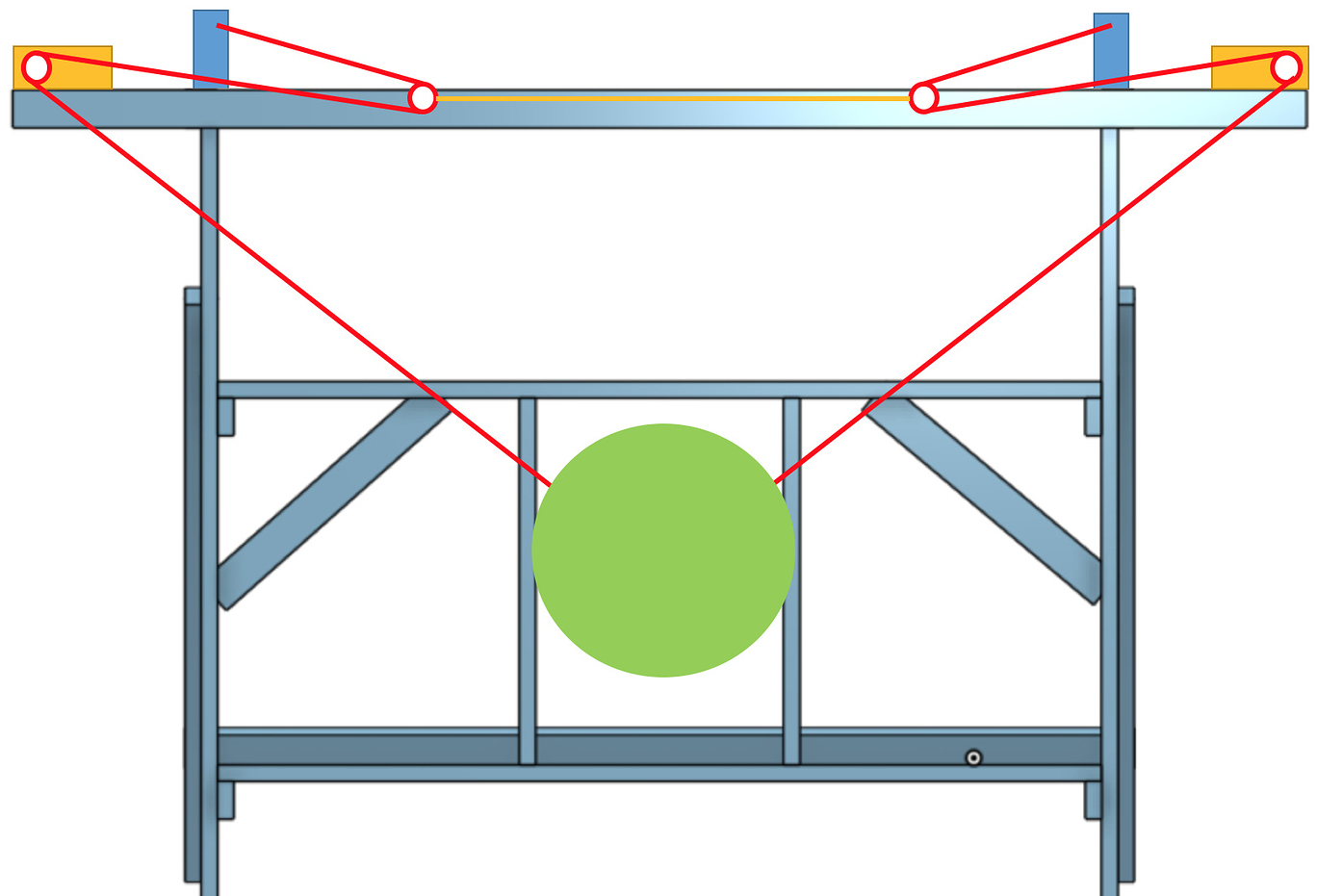
Chains
Bungee Setup
This is the Eastbay recommended setup
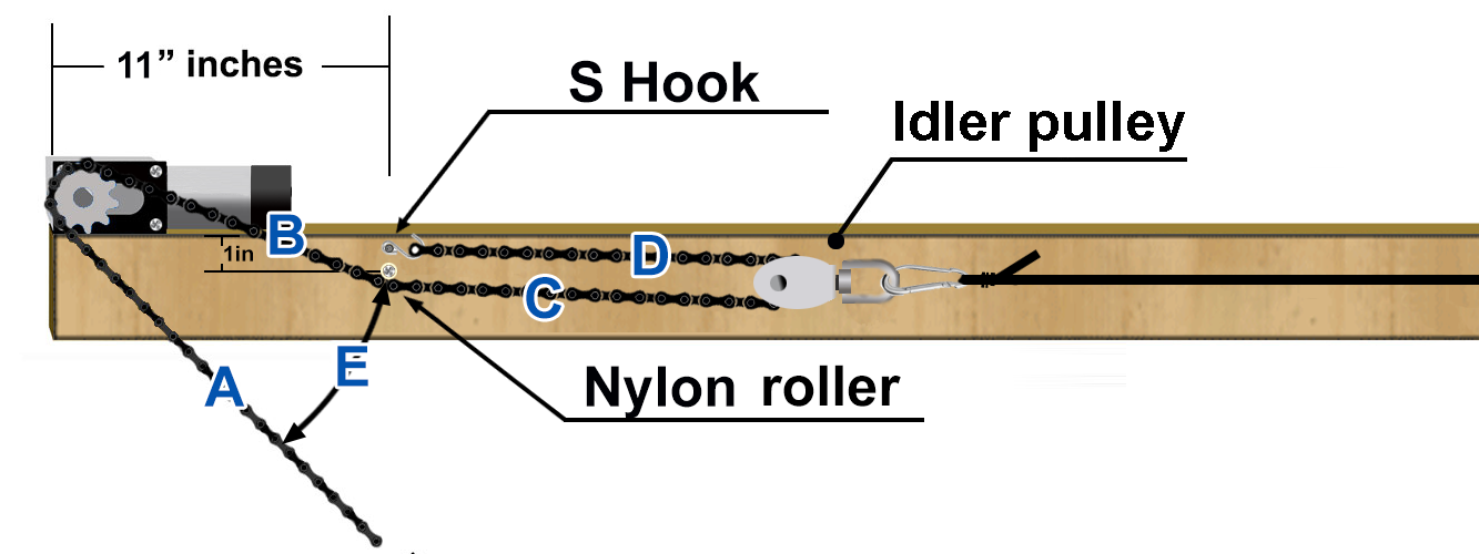
Having a constant feeding angle (B) ensures more chain-sprocket engagement and NO chain sideways or front/back oscillations - longer chain hanging in air could lead to unwanted oscillations and misalignment while feeding which will increase the chances of the chain skipping a sprocket tooth or coming off of it
The nylon roller is 11 inches from the left edge to allow enough room for the chain (A) to pivot (E) - especially when the sled is at the top corners - 1 inch from the top is ideal as it’s high enough but no to close to the top edge to splice the wood when installing it.
Putting the s-hook on the front face instead nailing the chain end on top of the beam as other set-ups keeps the entire chain in on plane - not forcing it sideways (which is not good for any chain) and not grinding the edge of the beam.
Shorten the bungee until the chain has tension when the sled is more than half way between home and the motor location.
Counterweight Setup
Counterweight is a good way to keep constant pull on the chain slack and is very easy to implement if wanted - Just keeping everything as it is, put two screw eye in the middle of the front face (top beam) then loop the cords from the idlers down and towards the back of the spoil board, then hang the weights - a couple 4 x 4in hdpe thin plastic sheets (out of a milk gallon) in between the cord and wood (where it rubs) will prevent it from ever wear out.
Chain guides to avoid gear jumping are an option. Be sure to mark your chains after they are fully extended for that one time when you have to reset the chain lengths. This will save you time from the entire recalibration process. A sharpie mark or nail polish on the chain over the 12:00 link after the first extension will save much time later. Additionally, when hanging the sled, use the second roller. The one with the pin in it, NOT the first one because the first one can come loose. There is risk of creating a pendulum out of your router and the only time it will tell is doom.

Common Issues
Many are having issues with chain wrap or chains skipping a tooth. This a problem with one of two likely causes. The first is the chains from the motors must run parallel along the face of the work piece to the sled. If the ring is too high or too low, the motors must be moved in or out to prevent the chain from binding since the chain does not bend sideways. The ring is placed at the right height so the sled hangs at 15 degrees to match the frame:
 Similar to number 4. Then the motors are mounted out from the frame to keep the chains parallel to the work surface. This will avoid wrapping chains or skipping teeth.
The second problem is likely chain tension of the leftover chain not being used. There are several options for dealing with this. The under configuration uses bungees. The stock bungees are too long and must be shortened or the chains can wrap. There are many scenarios devised for chain management which include springs, pulleys, weights, etc. Some pictures are included below. The goal is to keep the unused portion of chain out of the way of the motors and the sled, with not too much tension to affect accuracy of the cut. By switching the chains to an “over” configuration, the weights can be moved to the outside of the frame.
Under options:
bungee


Over options with weights:

(mounted on slides)