Bump, just to see where the Triangular Calibration Cuts are… I’ve got a >90% calibrated machine, have we established a procedure to get that last little bit together (specifically, where are we accounting for the chain segments added to attach the triangular kits?)
they are part of the ‘rotation radius’. rotation radius is the distance from the
bit to the center of the link that you put over the 12 o’clock sprocket pin. The
system doesn’t care how much of that distance is ‘extra chain’ from that point,
how much is space inside the ring, how much is whatever. It just cares ‘The
point that was at 12 o’clock is X distance from the center of the bit at all
times’
Hi all, I like the calibration concept and it reminded me of the Bowditch method I learnt for calculating open and closed traverse misclosure. I wondered if the Maslow might be able to record its encoder positions as it traversed to later account for errors using either Cartesian/Polar coordinates for comparison to a datum file? What struck me is that Bowditch is a surveying method is all to do with accounting for errors might be scaled by recording distances and azimuth, as cut, modeling the resulting closing error which is clearly present in many of the above diagrams above. Bowditch applies corrections to coordinates allowing even a possible second or third stage of calibration be performed further reducing distortion. Supplementry Question: do Polar or Cartesian coordinates cut faster on the Maslow?
The problem is that the maslow movement is not a polar or cartesian machine
the encoders measure how much the sprockets have rotated, that can be roughly
(due to chain sag and manufactureing tolerances) translated into chain length.
we have no way of knowing where the sled actually is.
we can make marks, have people measure the distance between things, and then
make calculations as to what the actual error values are.
But we can only do this if we have the correct mathamatical model of the
machine’s movements, and can figure out what measurements are worthwhile to have
someone do manually (remember, the accuracy of a manual measurement is at best,
0.5mm, so we have to figure out how to set things so that the error gets
magnified as much as possible)
we welcome any improvements, but it’s not as easy as saying ‘measure your error’
@Borderline That is a really interesting idea! I’ve been looking into lenses correction techniques but they aren’t very applicable because the errors they measure are usually spherical. Do you know of a good reference for explaining the Bowditch method to to someone without any background? All the sources I found were reminders on how it works for those who have done it before
A curious thing math! @bar I will scan you some pages and email them to you (book is probably still in copyright after all these years)
I had also been reading through the image/lens distortion and realised that GIS might have already found methods for dealing with images/raster/grid/surface irregularities for preprocessing satellite imagery. Ta NASA/USGS!
Also a further possible vector method might include a triangular irregular networks again Maslow traverses a datum path, records it encoders information and maps actual to datum yields the error and applies a correction.
Maslow needs a datum or known point (x,y) (Bottom Left Corner of the sheet etc) then traverse to points A,B,C…H etc. see image one
At each node (A,B,C etc.) Maslow creates different internal/external angles and these can be measured using trigonometry because the lengths of each chain should be able to be derived from the encoder output. I also had the thought that if the velocity of the sled is constant throughout the time taken for the calibration the distance travelled might be able to be derived (aka distance = time * velocity).
I have drawn up a hypothetical path and how the maths of closed traverse work in image one.
The second image shows the variance in distance in blue and there is also a subtle difference in external/internal angle, also very useful for the later corrections.
Another idea would create a triangular control network between each of the nodes for comparison to the actual cut path.
how do you accurately mark where points A,B,C,etc are on the sheet? and
especially how do you make sure those points are in the right place relative to
the motors?
since part of the chain is wrapped around the sprocket, how much chain is
actually out depends on what the angles are, which depends on how far apart the
motors are, in addition, the linkage kit effectively adds length to the chain
(which includes the slop in the chain, a couple thousanths * 500 links adds up
to a significant amount)
and the actual distance from the sprockets to the bit will also vary based on
the sag of the chain.
It’s these distances that the current calibration process is calculating.
You don’t need to know where A, B, C are physically on the sheet. using this method Maslow should only need to know that it is starting at the correct datum. I would imagine that the gcode file .nc should have all the nodes configured (preferably with a triangular control network - think Voronoi) with predetermined angles and distances inbuilt for reference. an optional z-axis operation might occur when it reaches the node if tangible testing is required?
I omitted this step in previous posts: at the end of the traverse, the sled returns to the datum (or what it thinks is the datum) and this is where the operator measures the error (or mis-closure) and applies the Bowditch corrections to the device settings. The method is repeated until the error is sufficiently reduced. I hope I am not confusing anyone too much the maths is sound (property boundaries depend on this technique) and the method should scalable to the unique circumstances of the Maslow.
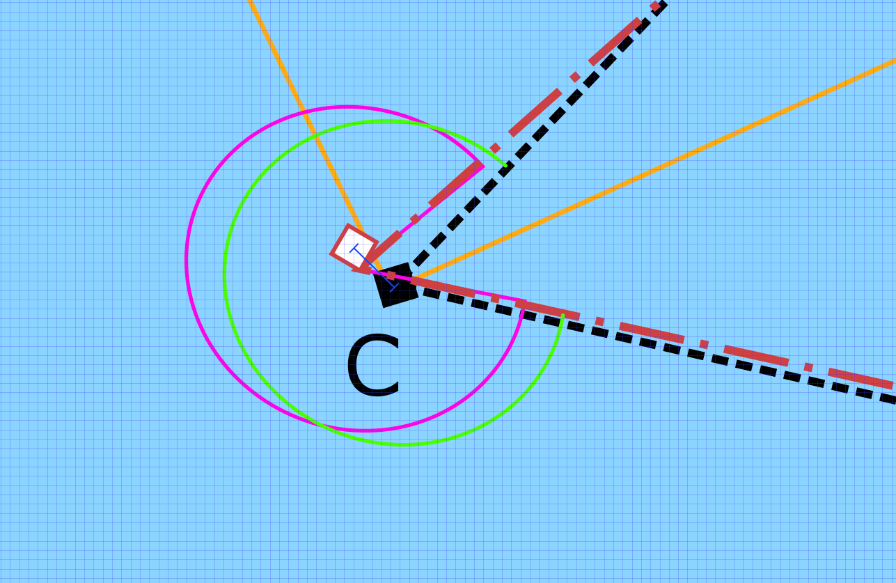
Does this next image marry what you were trying to convey where there is a dynamic point on the sprocket where, depending on the angle the chain, has its zenith contact point?
the maslow is very repeatable, if you tell it to go to 1234,3424 it will go to the same point, no matter where else you have told it to go in the meantime (the motion is not relative to any fixed point), so going on any path and back to the same coordinates will now show any error between your start and finish points.
so your problem is how to know that it’s not where it is supposed to be at the various other points you stop at.
your diagram is close to right, just remember that the ‘start of the chain’ is the top center of the sprocket.
There is no symmetrical inverse at the other end, there is an unknown amount of extra length added to the chain (but the same amount added to both sides), some amount of ‘stretch’ to the chain that’s left the sprocket, and some amount of loss of distance on the calculated length because it’s a curve, not a straight line.
you need to do two things
draw out a machine, showing all the details of the chains
go through the math in the source to see what things it’s taking into account.
Then you will have a better understanding of the problem space and the calibration problem
This is a really really interesting idea. I can’t say that I fully understand it, I’ll need to do the reading, but I can see the similarities between our situation and surveying. In both cases you have a system of measurements each with some error. It sounds like this system lets you improve the accuracy of a measurement by taking more related measurements and treating them as a system which would be powerful.
I am looking at your image of the chain wrapping around a sprocket. Yes the length of the chain changes due to the wrap, radius X angle. This can easily be corrected for by mounting a fixed sprocket of the same number of teeth, same radius. on the sled instead of ending the chain at a bracket. The angle of wrap for the sled mounted one is identical, length of wrapped chain identical, to the drive sprocket or if put incorrectly doubles. For the correct position a line between centers of the two sprockets is parallel to the chain. And the length of the chain is that center to center distance, always.
If this is the case and the algorithm using the sprocket center line in the formula so a 4 bar linkage is created with the distance between the center of the drive sprockets on the frame and sled fixed then all of the fancy rollers and rings are not needed. The accuracy of the sled is the accuracy of the remaining two lengths calculated. The weights on the sled keep fixed length linkage in parallel to the fixed frame linkage that is horizontal. Four bar linkage have tons of articles covering the trigonometry. The program uses the Cordic algorithm for calcuating sine, cosine, and tangent which is a short table and a program to add or subtract and shift bits to get to any precision desired. .
 imagery. Ta NASA/USGS!