I was thinking we could switch to motor controller chips commanded over SPI. That way we wouldn’t need so many pins
Yes it is. I’m an idiot.
Turns out I should sleep more.
1 Like
Interesting design iteration @bar, I am a fan of your ideas to consolidate the mechanisms of the project into a smaller package.
When reading the OP, the same ideas and advantages that @pillageTHENburn presented came to mind, so reading the exchange between them and @madgrizzle was thought invoking. Primarily, the tension system using springs and the division of labor between components. It is important to consider that a great motion system may be a poor storage system, or an inaccurate measuring system.
There is a lot of merit in using spring-reels to load and hold the extra cabling on board, providing tension to keep the sled in place as well as relief from the amount of work the motors must output. This system bodes well to the future improvements as well (speed!!), as instead of eventually being held back by motor specifications we can offload some responsibilities off the motor and on to ‘dumb’ mechanisms.
The cable feed issue can be solved by giving each motor a dedicated spring reel for the tension held on that line. This works on both a shared (2) or spooled (4) cabled design. In the case of shared, the spring reels are connected in series and will find equilibrium based on the specific feed of each motor. To be clear, they will expand and retract the cable on demand, consequently putting more tension on the rope when more total is extended, and less when retracted.
I am fond of the idea to only use two shared cables for the gantry, but the benefits of the reduction of reel-estate (sorry) by eliminating the redundant cable length needed to travel have yet to be seen, considering the complexity involved with physically sharing the cable across the sled. More brainstorming needed on this front. Diagonally sharing cables logically makes the most sense but for simplicity sake there is no reason the cables could not be shared horizontally, reducing the cable ‘traffic’ on the sled and eliminating crossing cables.
Accurate kinematics will be important as always, so my first hunch is that having fixed anchor points will not work as the center of the sled may differ from the triangulation of the tethers. Linkages are an option here but again increase complexity to route cables through a linkage assembly.
Good work guys exiting developments. Currently working on the building the OG Maslow, pics to come soon.
2 Likes
It’s been a few days since the OP, and it took me a while to read through the posts. I haven’t followed all the links ya’ll have posted, I’ll need to do my own research.
My very first thought when Bar described his new concept, was those flying cameras at football stadiums, not drones but the ones on 4 lines. Until I read this thread, I had only thought “those are cool”, never contemplated that those systems had a name like CDPR. They move fast and stay on target. Then there was the description of the 20m telescope with amazing accuracies. While the stadium cameras are most likely digitally controlled by a very skilled operator wearing some insane gloves and high tech goggles (less high precision necessary), the telescope system must be more of a CNC control to get that precision. Either way, those systems must have a very accurate way of determining cable length. I like the idea of multicolored line to index the length, that would eliminate issues of how many wraps on a spool.
Regarding cable tension, Maked_Potato mentioned variable tension. His description sounded a lot like a retractable pull cord on a gas engine. Surely spring coils like that could be sourced for fairly cheap.
I believe (though I haven’t done the math to prove it) that if the sled remains vertically oriented, then you can solve the math with fixed anchor points being used. It appears to be straightforward trigonometry. Alternatively, if you knew the rotation of the sled via a sensor, then you could also solve the math. The advantage of fixed anchor points are pretty obvious, but keeping the sled vertical and/or accurately determining the rotation of the sled may not pan out. I think a linkage kit would be the safe play from development perspective if only one idea were to be explored…
Correct me if I’m wrong, but the choice of the current motors was made in order to keep the cost down(?). With the addition of two motors, we are definitely increasing the cost. But I wonder how much of a cost increase it would actually be vs. using something like stepper motors? Are we talking another $50 per motor with gearbox (total $100 per motor) in order to move over to steppers or is there something else to it?
As I understand it, one of the challenges with moving over to grbl is that the current motors aren’t supported and someone would have to write that into the code. If that part can be eliminated and only incorporating the kinematics had to be dealt with, it becomes more feasible.
Yes, that is effectively what I was talking about for providing back tension for motors/capstans.
I think the “block and tackle” idea I mentioned also has some merit (or maybe didn’t mention? I can’t seem to find it). Since we are only dealing with ~26" of cable/rope if the slack is shared along a couple spring loaded pulleys I think we could effectively deal with the slack while maintaining a two-cable system. It’s difficult to explain but when I have some time I’ll draw a little picture…
3 Likes
You (@pillageTHENburn) are thinking along the same lines as how the Maslow currently deals with the slack chain, gravity does the work. One difference here though is that the slack would hang from a moving sled, potentially being dragged along and caught on something as it goes. We also lose the benefit of strain relief on the motors if we remove the spring-reels that pre-tension the cable.
Why do the drive cables have to be the measuring device? Why can’t they just drive and get position feed back from a linear cable position sensor. The motion transfer happens with some slipping perhaps but the feed back cables correct for that. The sled can have the cables quickly attached and detached each time a piece is loaded below the sled. That cable mounting position is easily repeatable. Even if you has to run limit switches in the four corners and have the sled calibrate each time it’s set up? Just a bunch of thoughts and I didn’t know if you guys are aware of the cable postion sensors. We use them in lifting heavy loads like bridges and house to keep the entire load level. 
2 Likes
No, that’s not what I’m suggesting. I’m sorry if it was confusing. I am suggesting post tension. This is what I wrote in my first post on this idea:
I only drew it hanging down like that to show you how the lengths work out. That drawing is to scale, so that is actually how much extra cord you’d have (around 26"). That slack should not be dangling in the air; they should not (and if using capstans they can not) just rely on gravity for post tension. Spring-reels were my first idea, but as @madgrizzle pointed out, without some clever tricks under the hood, two motors can’t share the same reel as I drew here:Musings on a new design - #42 by pillageTHENburn That was a silly mistake on my part.
BUT with a couple spring loaded pulleys the cord can still be shared and appropriate post-tension can still be applied. Since we’d be relying on simple (cheap) springs the tension won’t be linear, but in reality as long as the lowest tension (when the sled in on a diagonal line between two anchor points) is enough to keep the capstans engaged then it would be fine!
Again, I think with this concept the measuring should not be handled by the take-up motors. Perhaps a patterned cord with a pinch roller and an optical backup to account for drift/slip?
Once I have more spare time I’ll try to build a prototype to show what I’m talking about… That’s not likely until after Christmas ![]()
Thanks for clarifying. I have a better idea now of the system you envision, but pictures are always welcome.
A directory of sorts for the components and mechanisms we are referring to in this thread may be a valuable addition for people like me who are unfamiliar, so I’ve taken a shot at it below. Admittedly, I haven’t worked with these principals in depth before, so please correct and append me if needed, I’ll edit with time.

Spring Reels
are probably most commonly known for most retractable cables, hoses, and cords. They come in many types, sizes, and load ratings for different applications. Using a constant force spring, the reel is always under force retracting the line. There must be a resistant force (typically weight or a physical endstop) that prevents the spring from completely unwinding. Additional reading on these can be found from a manufacture at Hunter Spring and Reel Co.

Spools are simply cylinders which lines can be wound around. Spools usually include a bore through the center for use as a reel, but is not required.
Reels are spools with the inclusion of a bearing for rotation. Referring to a reel would usually imply that the spinning and winding mechanisms are included, and the reel only needs to be mounted for use.
Pulley is simply a wheel mounted on an axle used to redirect the load on a line or guide a taut line.
Sheaves are a style of pulley known for their grooved wheel that guides the line into place within the pulley.
Block and Tackle is a pulley system to use mechanical advantage on a load. Multiple pulleys or sheaves freely rotating on the same axle comprise a block. Two blocks, with the line attached to one and threaded through the other (potentially multiple times) create a block and tackle system.
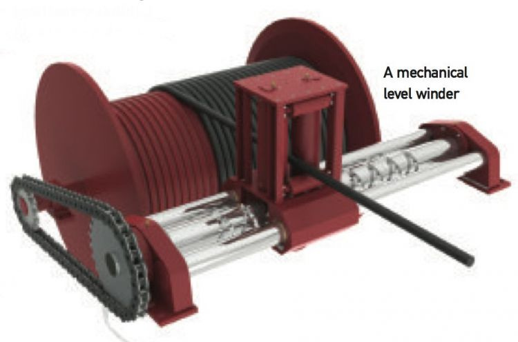
Level-Wind is a mechanism used to even and orderly lay a line onto a reel. Level winds distribute the line across the traverse a level winding on Depending on the use (measuring line with motor encoders), level winding is needed to achieve a consistent length of line being wound per revolution.

Capstans, defined simply, are used for winding in a line. This was a new word for me, and most resources I found refer to the nautical origins of the word. Capstans on ships use vertical cylindrical posts used to mechanically wind in a line, originally by the use of levers and mechanical advantage. There are different styles of capstans-- they be fixed or holding (ratcheting, one direction only). More readings, as well as the mathematics used to find the holding force of a flexible line around a capstan can be read about here Capstan Equation
Windlass is listed prominently alongside most nautical material concerning capstans. Windlasses are also used to wind in a line. The biggest defining difference is that windlasses are oriented on the horizontal axis. Both capstans and windlasses traditionally relied on man power for operation.
Winches are modernly synonymous to the windlass, being oriented on the horizontal axis. Winches are assumed to be operated by electrical, hydraulic, or pneumatic means.
I believe using two spring reels connected in series is still a possibility for our application. I don’t see spring-reels commonly used in the way necessary for our particular use, but it should be able to be done. I’ll have to draw it out or get some parts in front of me to prove it. It may have been a silly implementation on your part, but still a very valid line of thinking to solve our problem. It may lead others to more ideas and that is useful in itself. Your spring loaded block and tackle system can also be used to store and tension the excess line-- really worth looking into. I agree that the tension doesn’t matter as much as long as the lowest anticipated tension isn’t too low. In principal it works using the same as two series-connected spring reels.
I’m not sure the best way to achieve it, but for measuring we have some great ideas in this thread.
M.P.
4 Likes
sorry for the delays in responding (and sorry if this comes off as being
negative) having to edit my replies since I’m doing too many replies for the robot to accept
one problem with mounting the motors at the sled is that they need to be mounted
to the roller carriages (or linkage arms), which means that they will sag out of
the direct line with the bit due to the weight of the motor. To move faster, we
need more powerful motors (well, you can gain a bit by going to higher voltage
motors, but 24-48v is the best you can think about doing)
pulling in the bottom corner is still going to need to have enough angle to pull
well (if you are near one bottom corner, that motor will pull well, but as you,
move along the bottom, you need the other bottom motor to provide down force as
well, and near the middle you need both bottom motors to pull down) so that
means about 1.5-2.5 ft below the bottom of the workpiece
‘low stretch’ kevlar still stretches, a google search finds 1.5-4.5%. safe
loading is ~10% of breaking strength (hopefully this means little stretch) and
knots can reduce the strength by 50-80%
you can’t accurately calculate how much the line will pile up on itself, because
it does not stack evenly (and the stack will be different depending on how much
tension it was under as it was wound up), so measuring the line movement (pinch
rollers, or one loop around a roller, or optical) would be required.
Richard Green was exactly right, quote:
As the rope gets thicker and heavier, you will have less stretch and more sag
to compensate for. Thinner rope will give you less sag and more stretch. Same
for tension: Lower tension means less stretch and more sag, higher tension means
more stretch and less sag.
one problem with the 4-motor version is that the model is ‘overconstrained’,
which means that as errors build up in positioning, instead of it just resulting
in position error, it will result in tension errors, which can cause the entire
machine to bind up if the tension gets too high, or make the lower motors
ineffective (reverting back to a classic maslow) if it gets too low.
you could try to avoid the linkage sag problem if you made the motors fixed and
prevent sled tilt by keeping the tension correct on all four corners. This would
solve a lot of the mechanical problems, but would re-introduce the math problems
(although with it being tension rather than balance with gravity, that may be
more easy to solve). Or it could end up being something that can be sampled
how does this shared line work if it’s near the top left or bottom right corners in your diagram?
2 Likes
an optical reader on a standard tape measure would be able to detect the movement of the lines and read numbers within the range of vision.
1 Like
hitting the limit of the number of replies, so replying to many posts in one
what is the max amount of slack cable you need to deal with? can you just have a piston that pushes out from the sled to take up the slack?
one problem to watch out for is the position of the cutting tool, if it’s not in the center (due to different diameter motors for example) you will have problems.
Doing something that cannot rotate (say a saw blade) is MUCH harder.
one problem with making use of the cable driven robot concepts is the fact that they assume empty space so the cables can go anywhere, that will hurt our use case.
but other than that, they are a good type of thing to look at, they spool the line at the motor (no overlap)
| issue | stepper | DC/gearbox/encoder | BLDC/gearbox/encoder |
|---|---|---|---|
| power | low | med | high |
| controller | high | low | med |
| effort/rev | v-high | low | med |
| position stability | low | high | high |
| price (low power) | low | low | med |
| price (high power) | high | med | med |
| plus there is the open-loop vs closed loop question, with encoders you know if things moved or not, if you have a high resolution encoder, you don’t need the high number of steps a stepper provides (in fact, it’s likely to be more of a headache than a help) |
we haven’t found a cheap linear cable position sensor. what do those things cost? how accurate are they? the last time someone looked at them, one that was accurate sub-mm ran something like $700 per sensor
https://www.alibaba.com/showroom/draw-wire-sensor.html
how long would we need them to be?
that appears to be the main cost limit
They need to be about 3m long with an accuracy of ~0.25mm
so looking at the first one that came up on the link
that lists an accuracy of 0.1%, which would be ±3mm for $100/sensor
here’s one that looks like it may barely be able to do the job for $500/sensor
with an accuracy of 0.3mm
the combination of long distance and high accuracy are not common or cheap.
David Lang
An over simplification but here’s bottom right:

Turn your monitor upside down to see it in the top left…
About 26" per cable (total 62"). And yes, the slack can be taken up pretty easily in many ways. This is apposed to 107" needed for each cable with a non-shared design (428" total). (see: this post))
1 Like
You could use two, shorter, more accurate, draw wire sensors per corner. One mounted on the sled and the other mounted outside the work area, they would meet in the middle and their measurements would sum. I haven’t done any research in that area but if a ~1.5m sensor could be had for cheaper then overall cost could be a lot less than long+accurate sensors.
Even though the cost might be slightly less the overall complication is greater because now you’re running wires to all four corners again (from what I understand we are trying to get away from that).
I’m confused, in the image above, you have one red line going from ap1 to the sled to ap2. when you say 26" of slack total, is that in the entire red line? so if you had a spring loaded piston that moved 13" it could handle the slack by being flat when it’s all fed out (in the bottom corner) and then fully extended in the middle (the shortest total ap1-ap2 distance)?
That seems very workable.
The error tends to be a percentage of the length, not an absolute value, so I don’t know that that helps you.
I have been assuming just two sensors (mimicking the original maslow chains) and finding the position via trig.
1 Like