Interestingly, it looks like (and I might be completely wrong) that you can run micro-python on one core and still run cpp on the other…
1 Like
So they could sell batteries and new remotes for the ones permanently lost in the sofa, along with all that spare change
3 Likes
Bart’s amazingly prolific. Haven’t checked buildlog.net in a while, seems I’ve been missing out.
His polar coaster maker is on my lengthy todo list. At least procrastinating waited until V2.
Did you know Bart invented/developed makerslide which lead to Ed Ford’s Shapeoko (and a couple new jobs for Ed at Inventables and Carbide3D) which begat the X-Carve and the SO2 and SO3? Bart worked at Inventables for 5 years after they took over makerslide sales and production. He still gets a royalty on it from the bio I found
2 Likes
that would be a very neat thing if it’s possible.
David Lang
… although the grbl-esp32 fork is running grbl on top of a tiny real-time OS,
so it’s not doing bare metal on either core.
it would be interesting to compare the two approaches.
David Lang
Here’s what I am thinking the BOM works out to:

The two place XH connectors are the only part which isn’t surface mount which is a pretty big bummer. Does anyone know of a good connector rated for at least three amps which is surface mount to connect the motors?
3 Likes
Whats the plan for mounting the ESP32? The ones you link from aliexpress are devkits with pins. Is the plan to hand solder them? The schematics for the devkit is readily available and there’s not much to it, component wise. Maybe just build it directly onto the controller?
Also, how about including an SD card for storage?
Will that power plug handle the current for five motors? What type of power supply were you envisioning? The teensy board I designed had two separate 12V power supplies (like the ones we currently use). This kept everything sealed (since my design had the supplies mounted to the sled) so saw dust wasn’t an issue.
1 Like
How about Phoenix connectors, those are pretty common, these handle 6A. It looks like the three place is as small as they go for SMD JST connectors. How about a shield drain on the third contact?
2 Likes
Those Phoenix connectors look quite nice. I like the extra pads on the side to make them more sturdy. Let’s use those.
I’m imagining going to 24 volts on the supply so we can get double the power for the same current. It should help us get more power out of the same size motors and keep the controller heat down.
What all would be required to have our own ESP32 on the board? It’s the Bluetooth and Wifi antenna design that scares me. Those can be tricky.
Another thing we need to think about is how to shield our SPI lines going to the encoders. I made an awful mess of a cable to see if I had any problems and it worked great, but I still think shielding those cables is a priority.
1 Like
The devkit pcb design files are readily available (eagle format iirc), including bom. I’m outside sweating rebuilding my porch or I’d go inside and look at it, but I suspect we can just duplicate whatever the have in the design files.
3 Likes
Better lose the 7805 then, that is a lot of watts to burn up in a linear regulator.
The H bridge name label has a typo DRV8873, not DRV7783
I think users might prefer wire insert blocks for motors and encoders so they can change wire length without messing with connectors. We’ve had good experience using Wago or Weidmuller on our robots. Personally I would prefer large solder pads to connect the wire directly, but not everyone solders.
2 Likes
Not in the BOM are things like pull-up resistors for the TLC5947 outputs or decoupling caps…
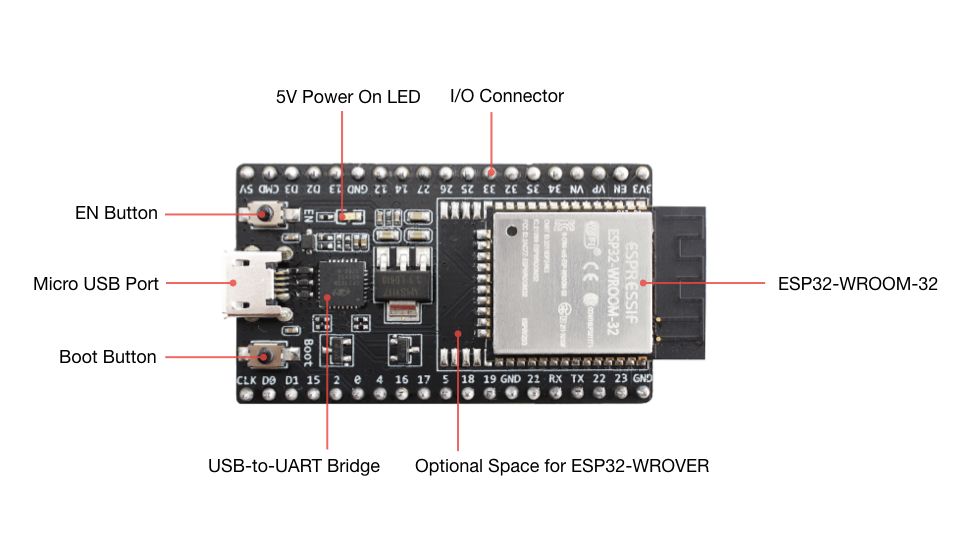
Using one of Espressif’s WROOM modules would take care of the antenna question, but leave the power supply, USB and reset&program buttons to place on the board. The combined cost of those would be more than the aliexpress price in the BOM. I note that the grbl-on-ESP board specifies the daughterboard, but leaves it to the user to purchase. It looks like the aliexpress board might be an earlier version, devkitv1. Not sure that matters but should be checked. The picture shows the antenna covered by the pcboard

as opposed to Espressif’s version Board.
ESP32-DevKitC V4 with ESP-WROOM-32 module soldered

Buyer beware…
3 Likes
Just a reminder that afaik there are no pre-assembled devkit type boards with more than 4mb flash. Only way to get that is use the modules and add the missing components.
go with a module, you can get modules with the added ram/flash and with both
on-board antennas or connectors for antennas.
the castelated modules are pretty easy to mount to a smd board and they
eliminate a LOT of headaches (including FCC device and antenna certification,
something we do NOT want to have to deal with)
David Lang
1 Like
Using a 6 position Phoenix connector in place of the JST connector would accomplish that, Phoenix makes screw terminal mating connectors.
1 Like
I’m imagining going to 24 volts on the supply so we can get double the power for the same current.
at least 24v, and it would be good to see if we can make the board support 36 or
48v for future use (if it’s only a few cents more for components, it’s worth the
future-proofing)
Another thing we need to think about is how to shield our SPI lines going to
the encoders. I made an awful mess of a cable to see if I had any problems and
it worked great, but I still think shielding those cables is a priority.
shielding or going with a balanced signaling so that you can use twisted pairs.
If the current capacity is there, see if we could go with ethernet cables. that
we we give people an easy way to get replacement cables or cables of different
lengths (for odd-sized machines)
David Lang
2 Likes
That might not be necessary, the encoders are transmit-only units and we have control of the SPI clock rate.
1 Like
![]()
![]()
![]()
Using a separately shielded pairs for Motor, 5V/Gnd, and encoder in a single cable would do that, or sepating the motor conductors from the others in a second cable.
Testing the encoder signal with the motors under high mechanical load/current draw will be interesting.
1 Like
I don’t know if it will drive up the cost too much, but putting in traces and holes (not sure about practicality of smd headers) for a stepper motor driver that can be optionally installed would be awesome.
1 Like
That would add a couple inche$ of board $pace, how about a header strip to put the step and direction signals on a cable, and move the stepper driver daughterboard off the main board?
1 Like