do you know if he accepts other formats? from onshape I can export to STL, Parasolid, ACIS, STEP, IGES, Solidworks, Collada, Rino, but not DXF
aaand just after hitting send I see how to export a sketch as a dxf (right click on the sketch and export)
now to try and see how that comes out 
for loading material onto the machine? or for some other reason?
for loading material onto the machine, put a hole in the top of the sled and
hang it on something above the workpiece.
to change the bit, release the catch and remove the router motor from the sled.
Actually, not having the sled pivot means that we need to cover more of an angle
on each side
with the sled not pivoting, the chain angle to the sled needs to be able to go
from just over 80 degrees (near bottom corner) to just under 10 degrees (far top
corner)
Well so far I have removed it frequently enough.
I am sure modifications will slow at some point, but that may take a while until the design settles out.
I also use mine with a track saw.
Maybe I am alone with this?
I, too. Every time that chain calibration is needed, for instance. Pretty frequent occurrence over the recent past.
Alright, it’s late and I’m tired and this was another throw-together test but I learned something about the linkage designs!
To test a possible bar construction technique:
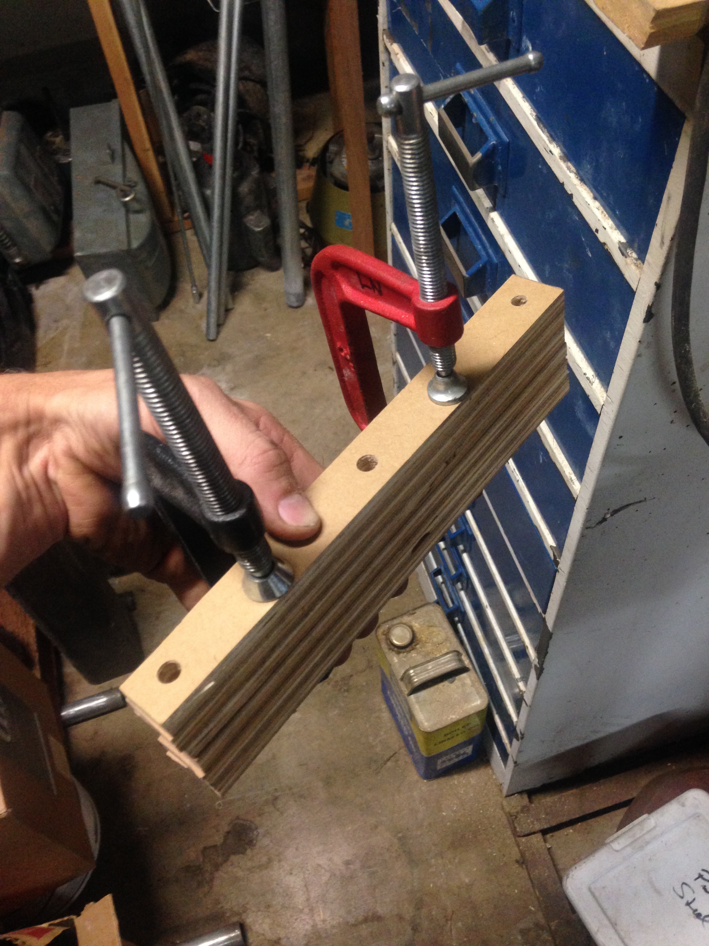
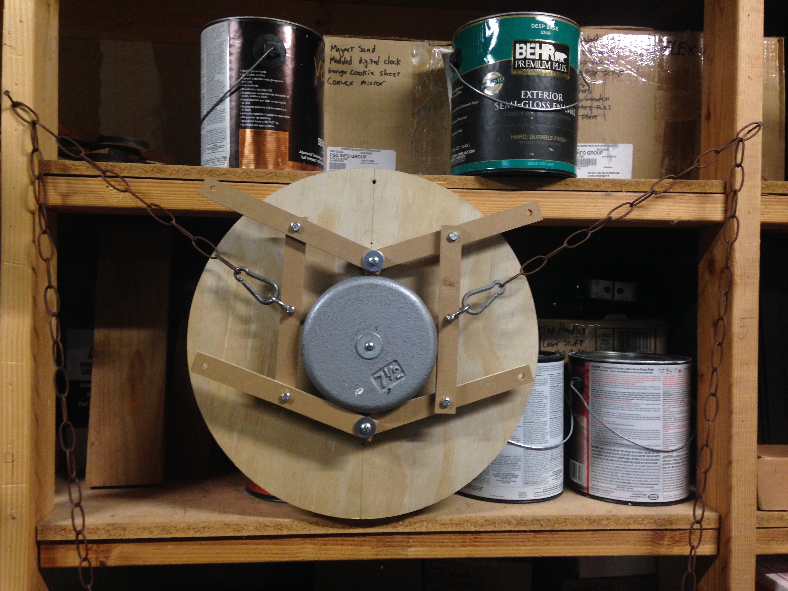
I cut 1" wide strips of ~1/2" plywood into approximately 9" lengths (using a hand saw to keep it real). I carefully measured and marked one with three points, each exactly 4" apart (starting 1/2" in from an end). I stacked all six bars and clamped them together with two C-clamps. I then carefully drilled through all pieces at the marked spots. I used a drill press but it could be done with a hand drill. Hand drilling will make accuracy more difficult here. I think this can be a sufficiently accurate way to make the bars but laser or plasma or water jet would be WAY better.
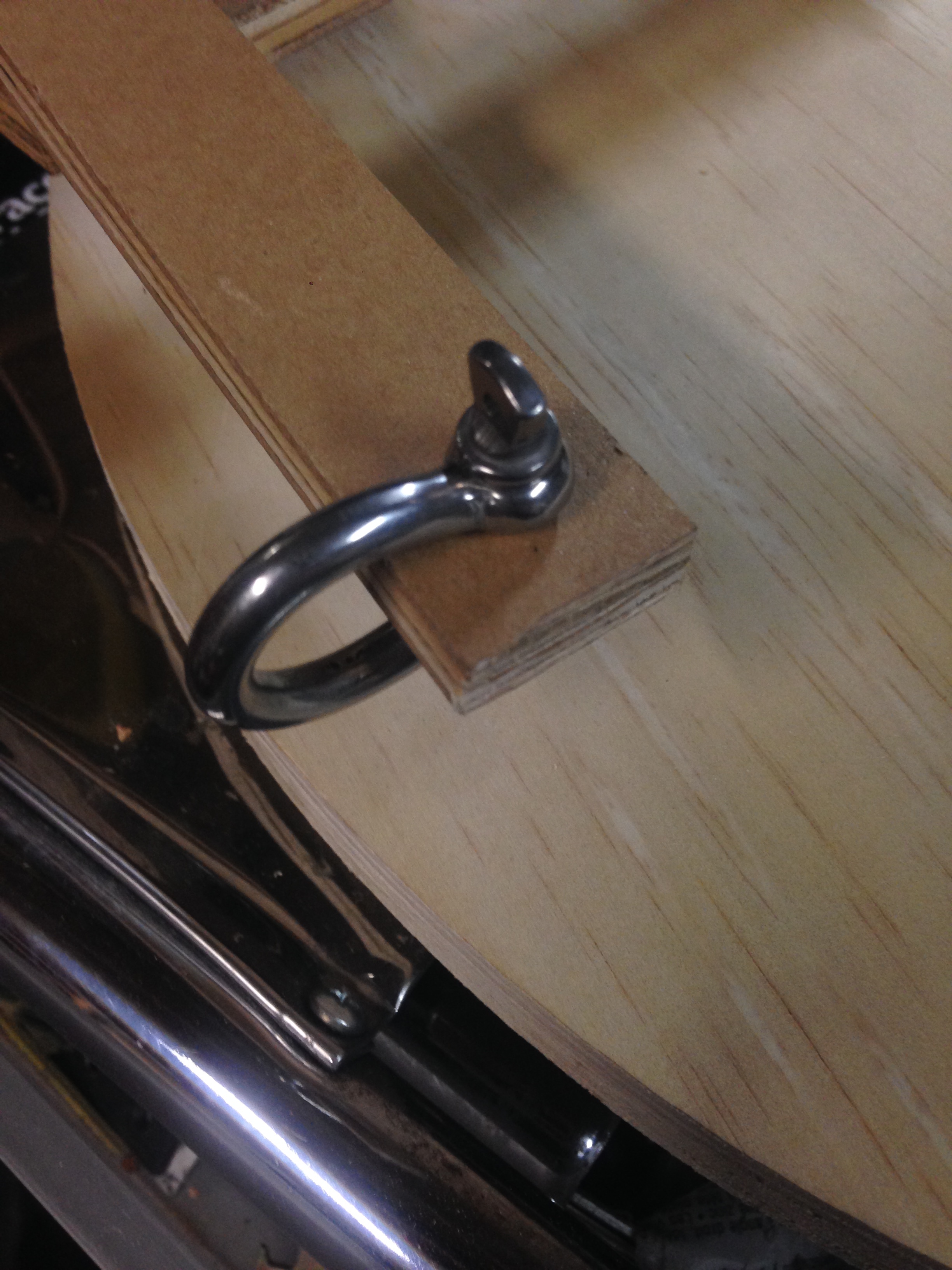
I used a screw pin shackle to give the chain rotational freedom while still using the hole in the center of the bar. This way you don’t need specially shaped bars. May still need refinement but this is much better than direct attachment.
I tried the 3-Bar Top Mount in two configurations and the 3-Bar Balanced. I wanted to try them both with the same materials and hardware at the same time so I could really see the differences in performance.
The biggest thing I noticed was that with the Top Mount design any error or slop in the joints added due to the compression-tension trade off. In the Balanced design any error or slop in the joints effectively cancel each other (they probably still lead to minor inaccuracy but it’s a consistent offset no matter where the sled is, with the Top Mounted one the compounded error changes based on arm angles and that’s not fun at all).
Of the two Top Mounted set ups I tried the one with closer arms felt slightly more stable.
I think you can see in the pictures of the Top Mounted one that the vertical arms are slightly splayed, this is the compounding error I was noticing.
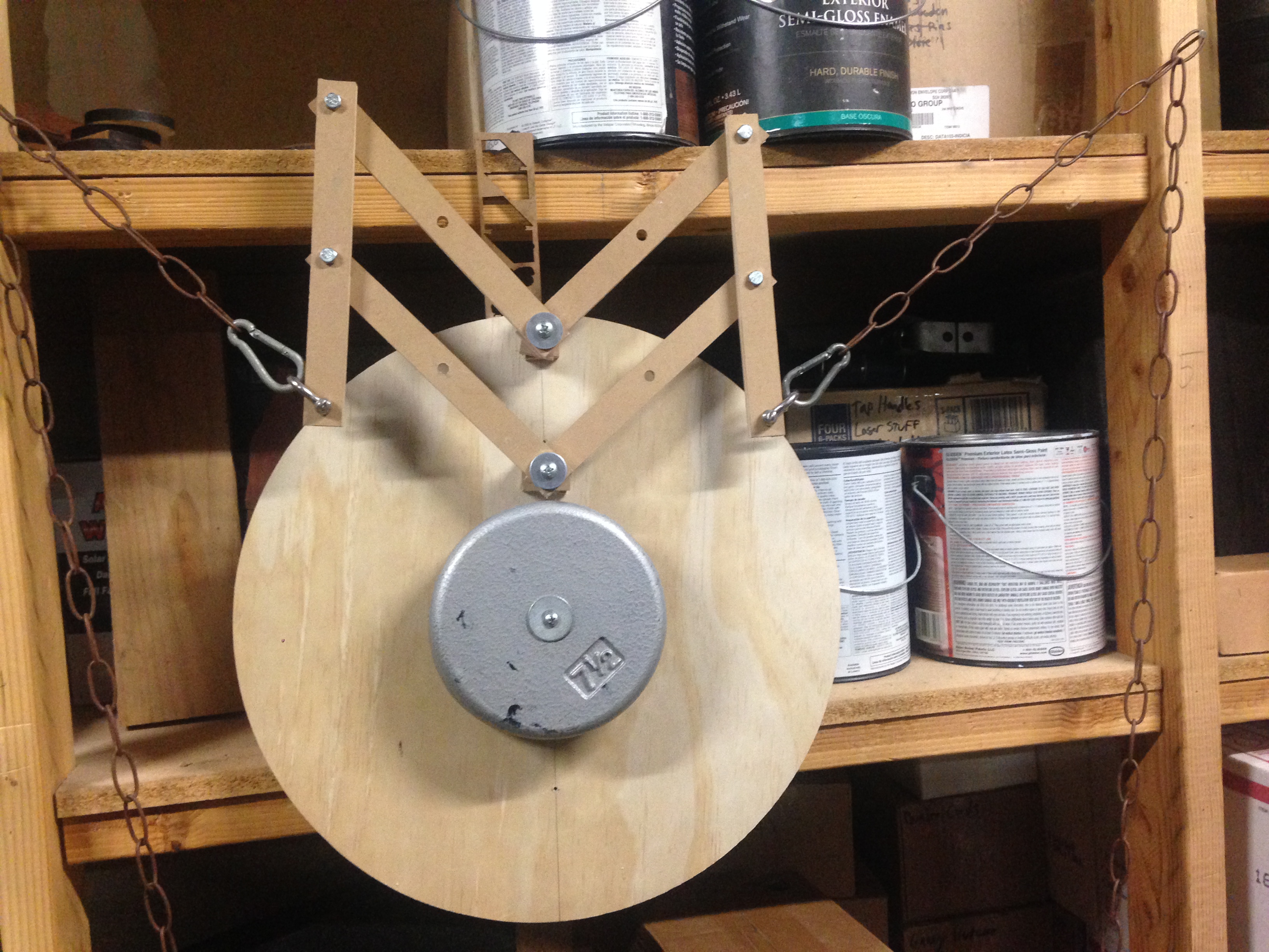
Even with my weights directly centered on the sled it feels quite “bottom heavy” using the Top Mount, [EDIT: after sleeping and re-assessing, I no longer feel this to be true. It was a perception when held in my hands but on the chains it is very well balanced) but with bricks on your sleds I imagine you’re already used to that. I just added 15lbs of weight in the center of the sled.
Another possible problem with either design (if stacking the bars like I did) is that the chain attachment points are not on the same Z-plane. This can probably be fixed and my not affect too much but it probably matters enough to think about it.
Here’s a far too small version of the Balanced design, there’s clearly not enough clearance with 8" spacing like this.
I just wanted to feel it compared to the Top Mount using the same weight and materials.
While I like the idea of the Top Mounted one because it can be made smaller and more compact, if I were to build myself one right now I’d probably go with either the Balanced or the 45° design. I just don’t like compounding errors!
5 Likes
I like that solution.
I know this is hard to characterize, but how much wiggle or slop in the joints do you feel? Was pushing the bolts through the holes a bit tight? I am trying to get a broad understanding for how quickly this multiplies to cause the error.
Were you able to rotate the sled relatively freely? I would have thought with your setup having all of the mass centered on the rotation point that it would feel very free. If it still feels significantly bottom heavy it might be an indication that the rotation point is not centered.
1 Like
One consideration on that is that the vacuum port on the Rigid router is between the handles, so rotating it 90 degrees would put that port on one side or the other. Obviously not an issue if you don’t connect a vacuum.
1 Like
I spent some time with it this morning (after getting sleep!) trying to figure out where the slop was coming from. There is very little coming from the bolts at the joints. I used these sleeved bolts I had laying around and I drilled to fit them pretty well:

While the holes are tight enough that the sleeve doesnt fall out they are loose enough to allow for rotation. There is very slight yet perceivable movement in the joints. After further inspection I don’t think much of my error was coming from those joints.
I think the biggest culprit is the anchor points to the sled. These are just large (3/8?) screws that go through the stack and screw into the sled. I had originally thought this might be a problem but it turns out with the weight its more of a problem than I expected. What happens is the top anchor point is pushed down while the bottom is pulled up and together they throw off the geometry enough to cause misalignment at the chain of just over 1/4"!
I used some spacers to hold the assembly off the sled but they were free-floating. This could probably be solved by securely glueing (and screwing) a solid spacer to the sled and mounting to/through it. That puts the moment of rotation directly under the first arm as opposed to 1" below it as is with this mockup.
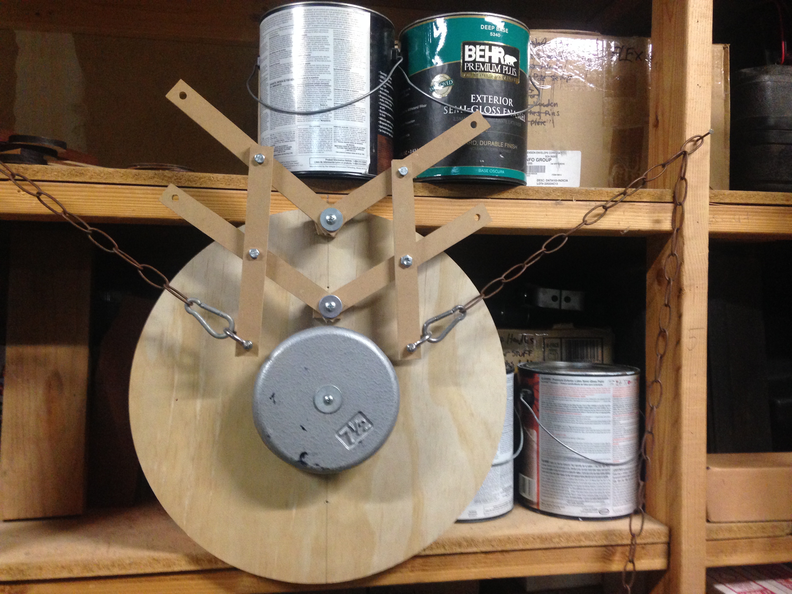
If you look carefully you can see that the two “horizontal” bars on the right in the image below are not parallel to each other. This is due mostly to the anchor slop.

I attempted to alleviate this by adding a piece of 1/4" plywood under the screw heads to force them to stay exactly 4" apart. This actually worked quite well and put this design back on the table for me. In the picture below you can see I rotated it pretty far and the horizontal bars are far closer to parallel than before (though they are still not perfect).

I believe that most of the remaining slop in this system is in the anchor holes; even though I drilled them the correct size they are not sleeved and I think the wood pushes into the threads slightly and allows misalignment. It’s pretty minimal and I think it could be solved with a smooth shank bolt, or a sleeve, along with solid spacer blocks (glued and screwed to the sled)
I think I mischaracterized this one. I think the impression of bottom heavyness was only when holding the setup myself (like, in my hands). When I re-visited it this morning it was apparent that the sled is quite neutral rotationally. If I rotate the sled it easily stays where I put it, there is no tendency for it to rotate back.
I hadn’t thought of that! Good call.
With all that said I think there are ways to reduce friction and increase rigidity without adding much work or cost. It might also be worth noting that it appears that if I lengthen one chain to the point the linkages touch the center weight (which represents a router) it doesn’t appear to throw off anything. Instead the entire sled tilts around the center axis and everything seems to stay aligned… This is just a cursory observation without the proper tools or set up to test it. So if anyone has made one with an actual Maslow (or at least not hanging from a shelf by nails ![]() ) maybe check to see what happens when things bind. It might not be as bad as we thought!
) maybe check to see what happens when things bind. It might not be as bad as we thought!
3 Likes
I bolted my spacers very securely and used 1/4 inch bolts. I don’t think I have much movement, certainly not 1/4 inch of movement
My center of mass is much lower, bricks at the bottom. If I force mine to collide I don’t see a dramatic sudden change, but I do start to see a rotation with a center higher than the bit. It isn’t huge, but we are talking about 1/16 accuracy, so I think it is enough to cause a detectable error.
2 Likes
I didn’t have 1/4" of slop either. The slop at the anchors was closer to 1/16"-1/8" (I never measured it), but I believe that is amplified through the system then added to the other side and in the end there was about 1/4" error, total, at the chain ends. I really have nothing to measure against so that’s just a guess.
we are aiming for 1/64" accuracy. I think that to get to that level, we will
have to account for chain droop, but right now we are facing problems where
people are off by 1/2" or more (depending on calibration)
that sounds about right. If the slop at the anchors is 1/8" on each of them, and
the vertical arms are twice as long as the space between the anchors, that would
result in 1/8" slop from each of them adding together to the 1/4"
This pantograph idea is very interesting. But isn’t Bar’s nautical hoop and some sailing blocks simpler? Is there a problem with that design?
I haven’t found an issue with it yet, it seems to work great 
I think the advantage of the pantograph design is that it’s probably cheaper to manufacture and ship or to build from parts you likely already have in the shop, plus it’s just a really really cool idea
1 Like
I haven’t seen a recent video, but based on an old video that bar posted, the rotation was a bit jerky. So far with my attempt, the rotation is very smooth and could easily be improved with some simple bushings.
That said Bar’s solution may have progressed significantly, making this less important.
1 Like
At this point we have 5 tested designs
- large bearings around the router
- Bar’s hoop
- balanced bar pantograph
- 45 degree rotated balanced bar pantograph
- top pantograph
plus my (untested) idea that we can cut any of the above in half by attaching
one chain to the sled and letting the sled rotate (requires a balanced sled)
All of these are doing the same thing from a kinematics point of view, they
eliminate the tilt of the sled and the distance down to the bit and the CG of
the sled.
At this point, we are trying to figure out the pros and cons of each of these
designs
#1 has the problem that good bearings are expensive and hard to get hold of
#1 and #2 both have the problem that you are trying to prcisely center a circle
around the router.
#3-#5 can all be built from wood, cut on the maslow (or by hand), or from metal
#3 and #4 have problems working around the router (#4 is better than #3)
#4 has a problem with the arms crossing, so they need to be mounted at different
heights (#3 and #5 are easy in this regard)
right no we are discussing how the errors creep in to #3-#5 nd trying to detect
any flaws (theoretical or practical) in them.
The pantograph approaches are going to be cheaper to build (no need for pullies,
or large rings, so cheaper in both materials and in shipping)
I think the pantograph approaches are going to be more forgiving of inaccuracies
during construction (hole placement, as long as the holes are all snug)
David Lang
2 Likes
Wonder how 608ZZ bearings would work for pantograph pivots? They’re incredibly cheap, and there’s over a hundred in the moosecave stash.
Press fit, either Maslow cut or a forstner bit, 5/16 or 8mm bolts. Hmm…
4 Likes
sorry for not doing pictures to explain this. I don’t have the tools to do so available at the moment, I may try later if needed.
Thinking through the accuracy issues a bit more, and I think the following is correct
the chain attachment must be even with the bit when the ‘horizontal’ arms make a right angle with the line between the mount and the bit (horizontal for the balanced and top mounts, at a 45 degree angle for the 45 mount). This means that the distance from a pivot point to the chain mount must equal the distance from the corresponding mounting point to the bit
so if a horizontal bar has holes A and B, the distance from where A attaches to the vertical bar to the point the chain attaches must equal the distance between where B attaches to the sled and the bit.
These distances do not have to be equal (the top mount is an extreme example of this)
For the balanced approach (where the mounting points for the horizontal bars are the same for both sides), there is a real problem because the horizontal bars need to go to 80 degrees from horizontal. This steep angle means that they will have to be curved, and long enough that the joint between the horizontal and vertical bars is above the router when at this angle. for a 8" long horizontal bar, this means that the bottom mount would have to be 1" below the router and the top 1" above the router. This would interfere with the dust collection. It may be possible to have a block mounted to the sled that lifts the arms high enough to be above the dust collection to clear and rotate the router, but this is getting rather ugly (and if the sled rotates at all, this fails entirely as the ‘horizontal’ arms need to get even closer to vertical)
I think this eliminates this approach from being practical.
For the top mount, as noted above, slop/error in the hole placement is magnified (slop in the bottom horizontal is pulled out, slop from the top horizontal is pushed in), the longer the distance from the bottom bar to the bit, and the smaller the distance between the bars, the worse the error. I don’t think the length of the horizontal bars makes any difference.
The minimum distance from the bottom bar to the bit is ~3 inches (this puts the hole over the edge of the base, but if it’s far enough up from the sled this can clear the base and handle projections. the r2200 router has a gap in it’s base on the top that can be used to squeeze a mounting block close to the bit)
This gives you about 5 inches that you can go to the upper arm.
with a 5 inch gap between the arms, you can’t quite go with 1" wide arms (they will collide with each other just before you get to 80 degrees), but with 3/4" wide arms you can almost get to 4.25" (4.253" in an ideal world, so 4.5" or more in practice )
with a 5" gap between the arms, an error of 1/32" in each of the 4 holes results in an angle based on a right triangle 1/8"x5" or 1/40" (0.025") per inch from the bottom bar to the bit, resulting in an error of 0.075" (almost 5/64") in the chain position. If the top mount is a little further from the bit at 4", this error would be 0.1" or 6.4/64.
in the balanced 45 degree approach, that same 1/32" error in each hole would result in 0.0625" (4/64") of error
if you can keep the errors to 1/64 in each hole:
the 3" top mount would have an error of of 0.0375 (2.4/64")
the 4" top mount would have an error of of 0.05" (3.2/64")
the 45 degree balanced would have an error of 0.3125 (2/64")
note, none of them achieve the goal of 1/64" accuracy, and there is very little difference between the close 3" top mount and the 45 degree balanced setup.
If you can make the spacing between the bars 6" instead of 5" (which would require a bigger sled, or a mounting bracket that extends beyond the edge of the sled), the 3" top mount results in errors exactly equal to the 45-balanced approach (4/64 with 1/32 error or 2/64 with 1/64 error). This makes me wonder if even more space between the horizontal bars would result in less error than the 45 balanced approach. I’ll have to think about this one.
if we are having the arms laser cut, it may be possible to cheat on the hole placement to counter expected error, but I doubt that would work well for all angles.
doing some quick google-fu to find standard machining tolerances, it looks like with a 1/4" bolt a ‘close fit’ would allow 1/64" of slop per joint, and a ‘normal fit’ would allow 1/32" per joint. using 1/2" bolts, the standard machining tolerances are double that.
we would need to get the error (difference between bolt size and hole size) down below 0.008" (1/128") to achieve the target 1/64" accuracy. At this point I start to wonder how much slop there is in the roller chain per link, even a thousanths of an inch times many lengths would add up, and this will vary over time as the chain wears. I’m beginning to think the maslow will ever hit the 1/64" accuracy design goal. It can get far better than it has been, pleanty good enough for woodworking, but I suspect that the final accuracy is going to be 1/32 or 1/16 when all errors are taken into account.