What a difference 1/10th of a millimetre makes (how I got retraction to work at force 3/4/500)
Following various different threads about binding / high friction in 4.1 arms (and @Rokhal’s posts in here - and noticing it myself), I spent some time investigating and freeing up mine - this is what I found and did.
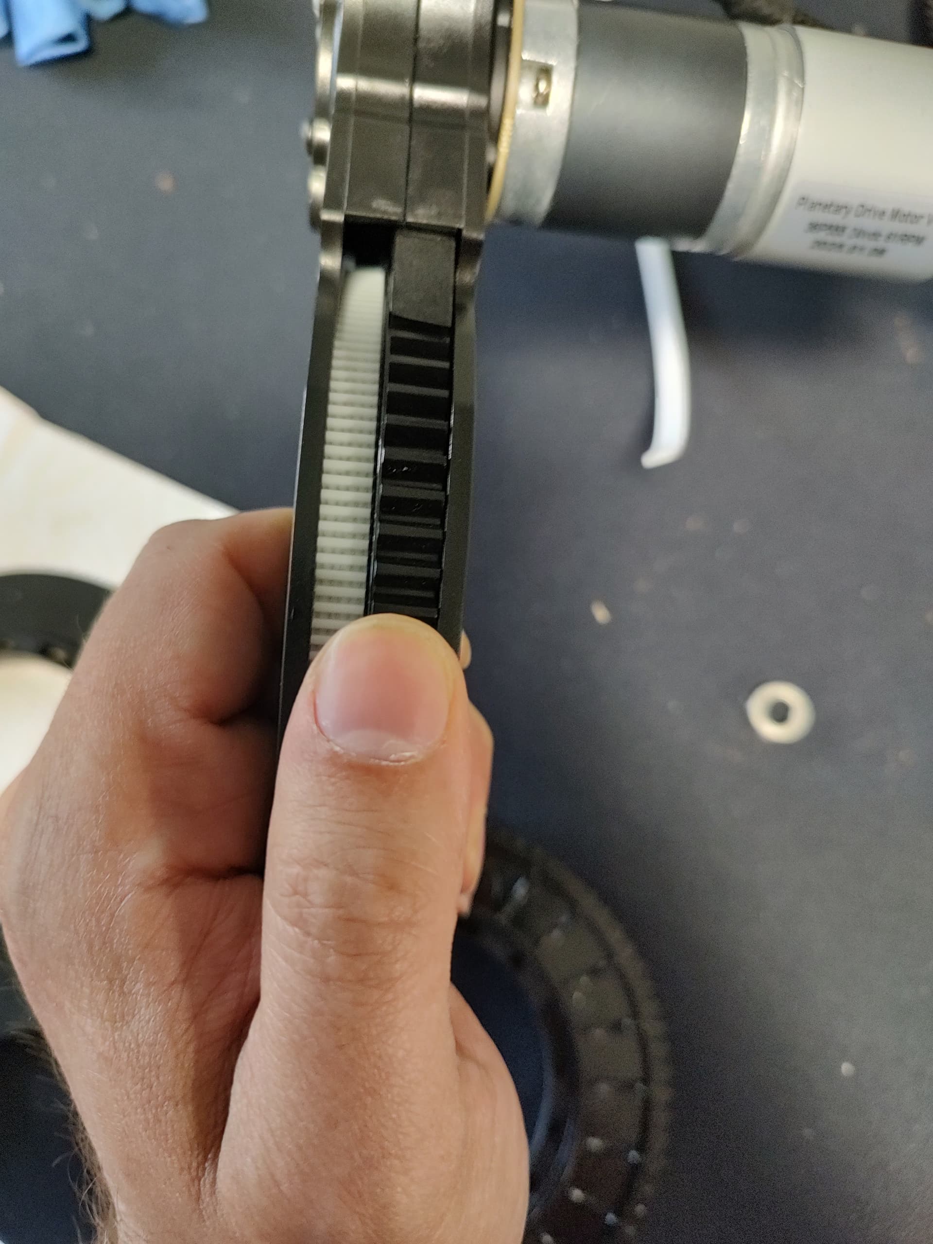
Note, you can check the amount of friction after assembly, there is a tiny bit of backlash if the belt isn’t retracted under tension - enough to rock the spool back and forward a few tenths of a mm with your thumb - it’s very noticeable when you can / can’t do it. If you’re not sure, you can easily extend the belts 10mm or something small and check.
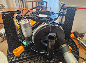
Ok, so initial investigations:
- I have a few spare 4.1 arms and reels, and a 4.1 that I took apart as part of this.
- I started with some basic things - measure everything I could with digital callipers, test different spools and arms.
- I had one arm in my built stuff I particularly thought was in need of looking at because of the bolts….
Initial findings
- I had different levels of friction between different pairings of arms and spools.
- In general, the topside of the spool (with the teeth) was tighter than the bottom, even accounting for bolt stuff.
- To the point of: the same spool / same arm spinning freely on the bottomside (belt side) and not on the topside (cog side).
- There can be just a few 1/10s of millimetres difference between too tight to turn and spinning freely.
- So how / where to sand? - lead me to Sanding Investigations below.
- The particularly bad arm was one with bolts rather than nuts, and I had to insert and remove the bolts with actual force.
- Leading me to Bolt & Nut Investigations below.
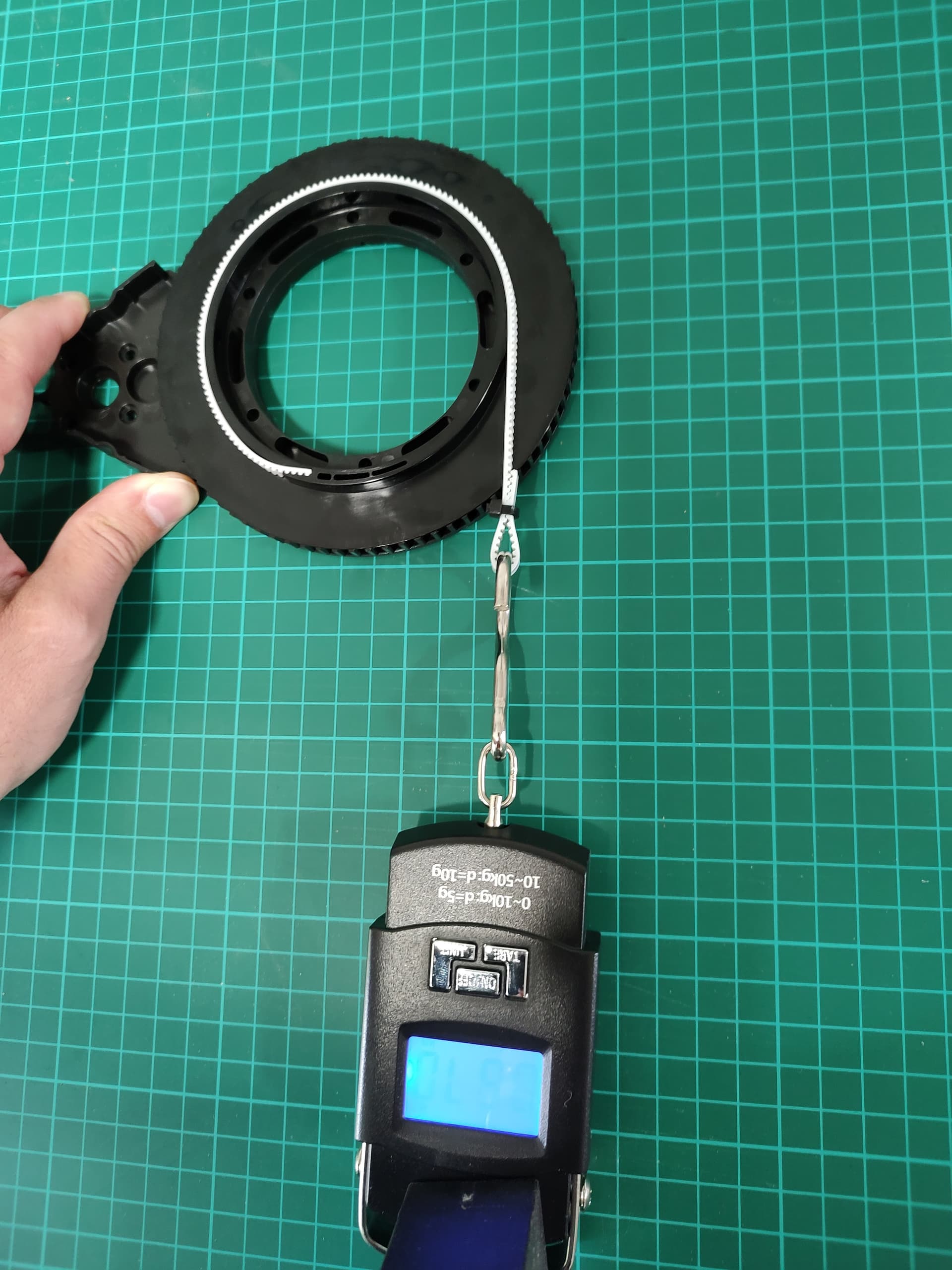
To give some indication of what kind of friction I mean, without anything bolted together I could see ~1Kg (so 10Nm) of force not turn just a spool on an arm:

Bolt & Nut Investigations
My thinking was - if I’m having to use force to put the bolts in, are they deforming the arm slightly and causing (at least some of) the friction? There has also been a bit of talk about having to crank the bolts down enough to engage the locknut end. Either way I went looking for some bolts with a smaller head and 14mm long.
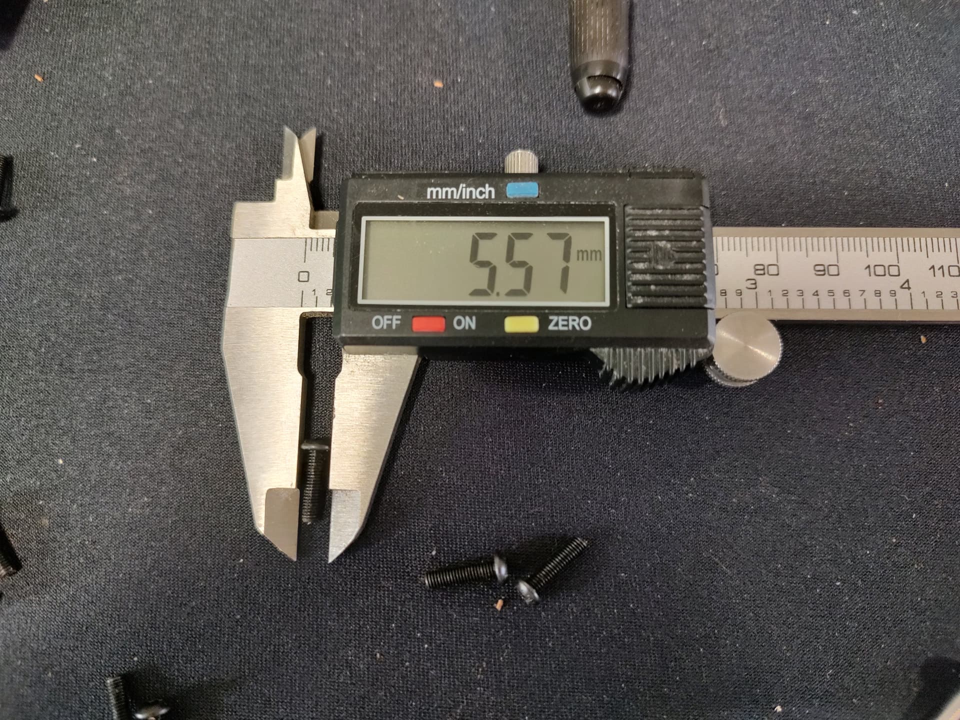
Note - my digital callipers are fairly cheap, so don’t assume the measurements are absolute, but it’s good for relative at least.
The stock heads were about 5.6mm:
Socket Head cap Screws seemed the best of the various I tried:


The ones in the last picture are the M3 x 14 option of these:
The thing I noted is all the listings give the head diameter as 5.5 / 5.6 etc, with a tolerance - these just seemed to be the ones that ended up the smallest when I got them.
With these - they drop into the bolt holes on the arm loosely, including the arm I had that was tight on the originals. They also allow the nut to be just tight and rely on the threadlock on the bolt rather than tension (i did whack a little blue threadlock on too just to be sure).
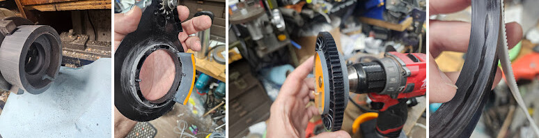
Sanding investigations
My initial measuring (and what I could feel) suggests the arms I have aren’t perfectly round in cross section:


Sanding a little shows this up quite well:
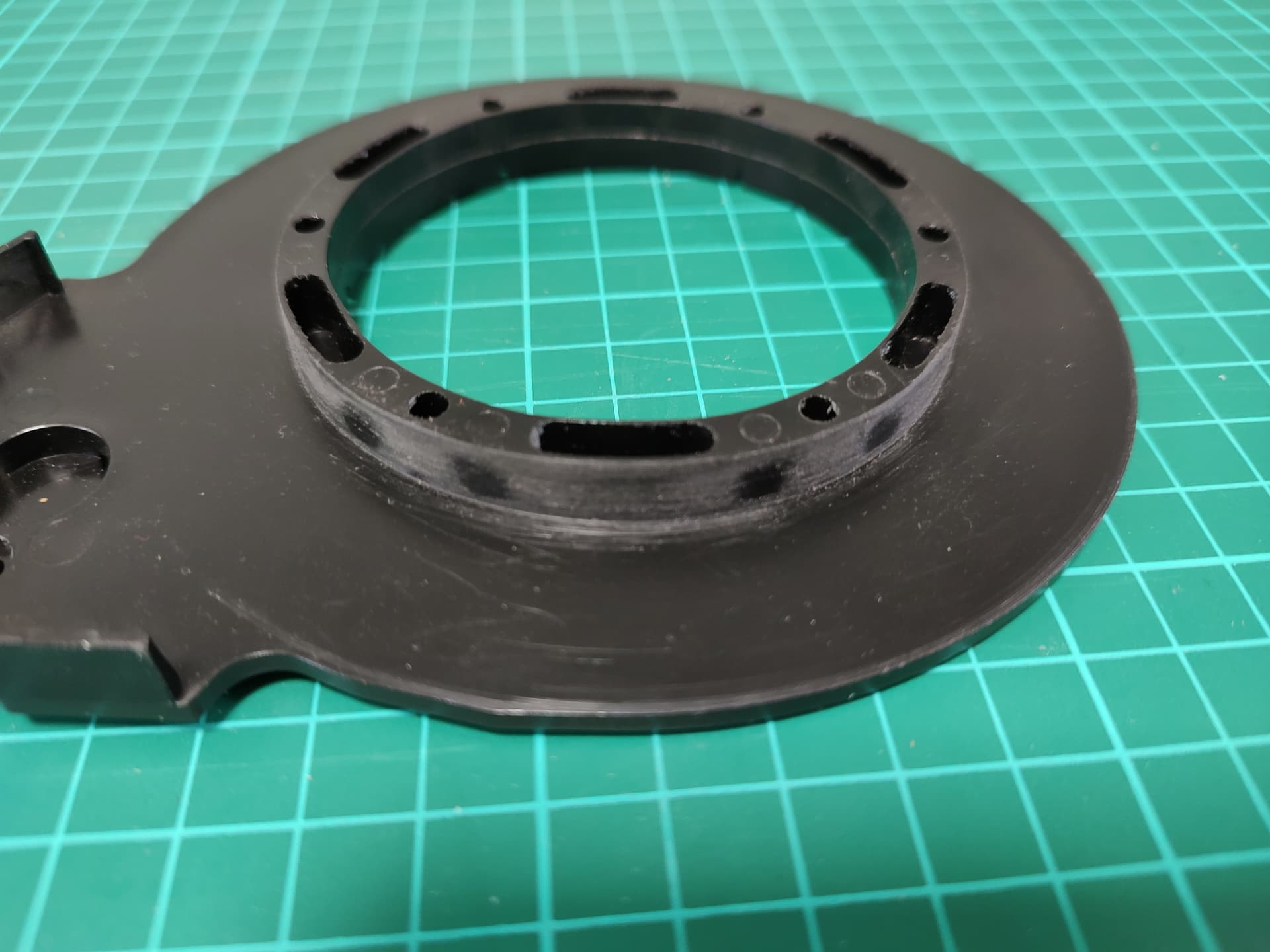
I wonder if this is due to different cooling rates for the different thicknesses?
So how to sand a slightly inclined cylinder?
I tried a few different ways. To try and keep the material removal to a minimum, I tried some valve grinding paste (mostly because I wanted a grinding paste and I had some lying round):
I just used a little of the fine, dabbed on with gloves, and just turning the spool on the arm. It works pretty well, but ultimately I ended up cleaning it up with wet and dry paper anyway, plus it’s messy, so I wouldn’t bother.
What really worked for me (like others), was wet and dry sandpaper - using 200/400 for material removal and 1000 to smooth (wetted). I tried both clamping the arm down to sand, and freehanding it. Not sure which was better tbh, I think freehanding is fine.
With that, I worked my way through all the arms as I reconstructed. I was being fairly conservative, sanding until they span with minimal friction, sanding the spool a little first, then the bottom arm till the bottom of the spool spun on that, and then the top arm until the top of the spool span on that.
I could have gone further so they were spinning completely freely / had a little play. I also could have added some wax / lubricant.
But with what I did I had one arm retract a little at 300, three retract but no quite the whole way at 400, and all retract at 500. Though i’d still use at least 600, and probably 900 for calibration. And while i’m still testing, the trivial calibration I did (running just the first set of points) was giving a very good fitness at 900 - I suspect 900 will work well for me this point forward.
Doing it yourself
If I was coming at it, either with a fresh build or doing a strip down to address this, I would do it like this:
- Fit the nuts in the 4 bottom arms.
- Fit whichever bolts you’re going to use in the top arms (unless you find some as loose as I did, then it doesn’t matter).
- Set up an work on each arm separately, you’re sanding to fit.
- For each arm:
- Sand the spool a little first - 200 or 400 until you’ve sanded the ridge in the middle and a little off the whole thing. Smooth with wetted 1000.
- Sand the bottom arm with 200/400 until it turns freely with the belt side of the spool (so as it will be when assembled). It took me 3 or 4 passes for most, just taking a little off each time. Smooth with wetted 1000.
- Sand the top arm with 200/400 until it turns freely with the geared side of the spool (so as it will be when assembled). It took me 3 or 4 passes for most, just taking a little off each time. Smooth with wetted 1000.
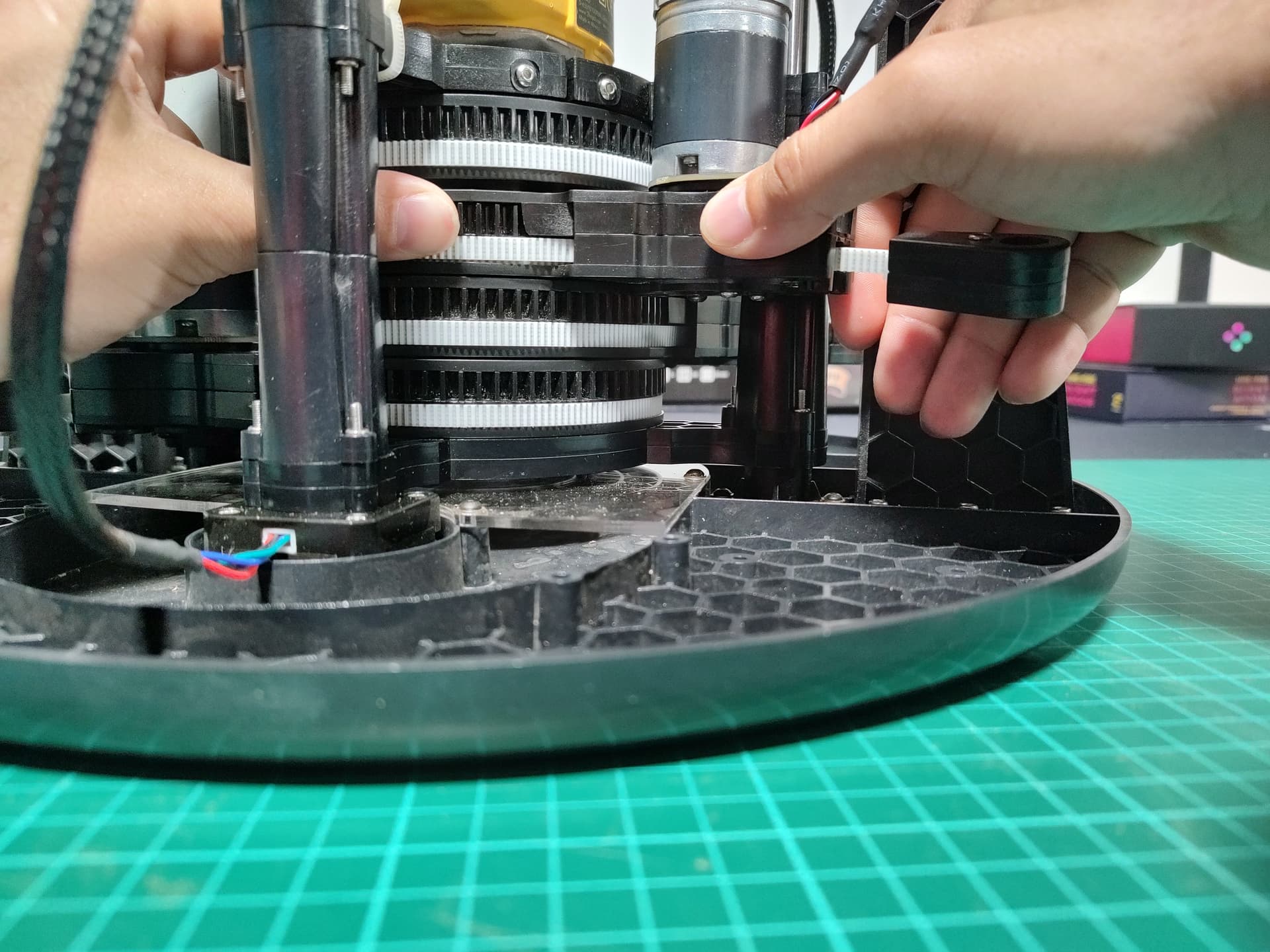
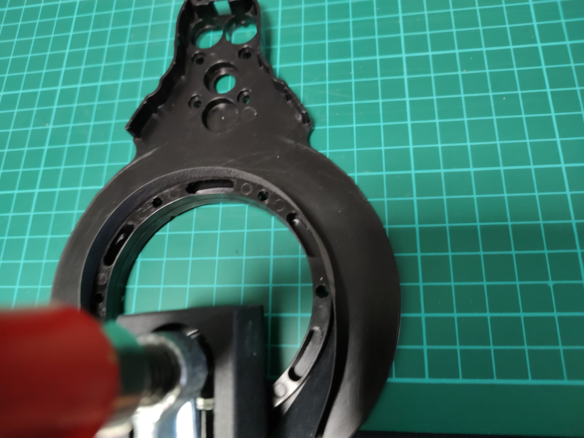
- Assemble that arm, without the bolts too tight, and check you can rock the spool with minimal force (see pic:).
- If needed, sand the spool or arms a little more until you’re happy.
Should be able to rock it with gentle force once done:
Hope this helps anyone that wants to do this ![]()