I think we figured out a way that is a lot simpler than what @theRatchet has come up with and you won’t have to sacrifice your ring. Checkout the Sled with Center Alignment Jig in the Community Garden. @Bar made a sample Jig, and place everything in the Garden.
Both the jig and my way use the same premise; that being a hole in the center of the sled that is ground zero for the router that everything is referenced off of. However the jig (which I like very much by the way) assumes that you have a way of cutting very accurately the reference pockets for aligning the ring to the center hole. It should get you close, but if you are off just a little or ring is out of round (which we’ve had some reports of); the question that @Dustcloud asked was how do you correct that? In other words, it doesn’t pass the test of the bit staying in the same place when you rotate the sled.
In thinking about it more since I cobbleminded up my idea… it probably won’t actually work… I think the mounting tabs on the ring or the brackets will get in the way of the router making the inside cut. You’d have to mount the ring at the upper most part of the brackets and that is the worst place to be for stability, which would be crucial.
When I was going to mount my ring I traced around the inner and outer ring to determine the radius and also to check if the ring was warped at all. I then marked the center of my base and drew in circles for the router base, the inner ring, and the outer ring.
I drilled the holes for the base large enough that I could use a centering jig to align the router to the base.
For mounting the ring I clamped the ring upside down on my base and then mounted the brackets aligned up to the ring.
With all the preparations I think that my router is darn close to the center piviot point.
Version 1.12 All with default Maslow measurements. Measured the left chain twice and was within .05 mm. 2.79 is a tiny better but 1.325 is considerably worse then my last benchmark.
At some point a stake must be placed in the ground. There are too many variables to account for and the more you analyze a problem, the farther out of tolerance it becomes. That being said, the sled template solves one issue for making the center sled hole concentric with the router bit… Solved. The 3D software placement of the holes for the ring kit accurately spaces the holes for proper installation… Solved. This is where I place the stake. Otherwise you must worry about how the ring kit was formed, are the bolts holding the ring kit, the router, z-axis all torqued and tension equally so the ring kit/router, z-axis are perfectly perpendicular to the sled surface. Then you start to wonder if the bit clamp is applying equal pressure all the way around the bit to keep it perfectly perpendicular and is the bit perfectly round or warped.
I understand that while we would like everything to be perfect, It just isn’t possible. So we correct the inaccuracies the best we can, but lets not try to overthink this. Even the best designs are flawed in some way or other. I say find a tolerance that we can live with for how far out of round our circles can be and shoot for that. Personally, if I can not physically see an imperfection easily with the naked eye, then I can live with the imperfection.
I should add that in no way do I think every ones efforts are for not, and I commend all of you for your time and energy you have put forth to make the Maslow CNC an awesome affordable tool. THANK YOU ALL!
we have people who are making cuts accurate within 1/16", while others are off
by 1/2" on much smaller cuts.
We are a long way from worrying about tension on screws and the Z axis being
exactly perpendicular.
Right now we have some sources of inaccuracy that we know about.
What we don’t understand is why some people’s machines are so much more accurate
than others, and that’s worth continuing to investigate.
We aren’t aiming for perfection, the stated goal is 1/64" but as long as we have
known sources of error that we can correct for in the math, we should keep
going.
Is the elephant in the room person-to-person variability, differences between individuals’ ability to accurately measure a distance? Can we get someone who is reporting highly accurate results, and someone who is reporting highly inaccurate results to independently calibrate the same machine? If the issue is person-to-person, the solution would likely be more deliberate process documentation and how-to communication.
Global comparing at same FW/GC and freeze till solved. Never done till date. (This would have been a radical suggestion, but I’m relaxed.)
So, a challenge (to much maths is boring).
The variables are known and although they are many, a mass of data will give a hint.
The calibrator of the week needs to be challenged.
Do we need to go as far to make GC upload the results, or can we deal with dropping the data somewhere?
I am planning to make a new sled and calibrate with 1.13 this weekend. I will upload the results as soon as I can. Also, will try spraying some silicone on the chains to make them as smooth as possible. Any other tips are welcome
I’ve got the automated process for computing the chain tolerances finished and it will be included in 1.14 1.13 which is released on Wednesday. The process asks for a manual measurement from the edge of one motor to the edge of the other then measures the left and right chains automatically.
It seems like it’s working properly because after doing the process to compute the chain correction factors I get the same number for measuring manually and for measuring in the automatic way during the calibration process.
The bad news is that something is still wrong somewhere with the way the chain calibration factors are interacting with the rest of the system because when I use my automatically computed chain calibration factors my accuracy drops considerably to 3.66-1.39 which is much worse than what I see after using the automatic calibration process with the chain correction factors set to 0 so I would still recommend leaving them at 0 while I keep digging.
I would be interested to see what chain correction factors the process computes for different folks to we can start to establish a range of what is normal. You can launch the process under the Advanced tab:
Hi Bar! Is the automated chain tolerance process separate from the automated calibration routine? If it is separate, and we recalibrate, is there any advantage to using chain tolerance routine if we still should keep the tolerance settings at 0? As I understand it, you would like us to use the routine, report our results, and then reset the tolerance values. Is this correct?
Yes, they are separate for now. When the new one works well enough that it’s an improvement over the regular calibration routine we can integrate them.
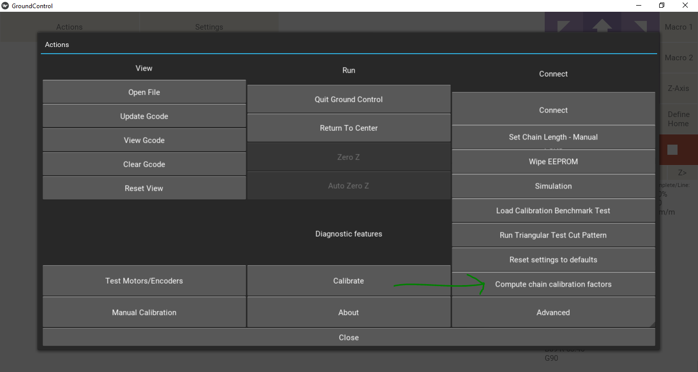
I recommend computing the chain tolerances by clicking Actions -> Advanced -> Compute chain calibration factors, snapping a screen shot of the last step and posting it here so we can see how similar our chains are, then setting the values back to 0 in the settings for actual cutting.
I just finished my latest calibration after creating a new sled using @Jayster technique shown here…
Seems to be a pretty solid improvement, as now there is about a 1/16" vertical deflection when rotating the sled through 90 degrees with the bit cutting .1 inch deep… the resulting hole is 5/16" high x 1/4" wide. I spent a lot of time with this build, and don’t really know how I could do much better working with wood screws and hand-held tools. Also, I was able to get a pretty accurate measurement of the “rotation radius”, measuring 119 mm from the center of the spindle to the outer edge of the ring. From the outer ring to the bottom of the roller bracket where the chain attaches is 20 mm, so a total of 139 mm, pretty much in the zone that is suggested in the cal routine.
I ran the Chain Calibration routine. I actually ran it twice, as it seemed like the chain may have skipped when it was playing out the first time, and the results were pretty crazy. I like the way it is set up, with the software calculating how much chain needs to be played out. A countdown would be a nice addition to give time to get to the chain/sprocket. I advise keeping tension on the “tail” of the chain, as links sometimes catch on the sprocket teeth. I have run the old “chain-measuring-motor-space” routine more times than I can count, and always eased the chain out in shorter increments, so the links never skipped. Having it all go in one run seems to increase the skipping possibility. Here is the result:
I then zeroed out the fields in the advanced settings, per Bar.
After recalibration, ran the Benchmark, and the results were better than I have seen up to now, although I only used my metric steel rule. Doing the metric conversions from my British units caliper was too much for me today… Here is the chart…
@Dustcloud thank you so much for running those tests and getting back to me. I’ve been anxiously awaiting your results and they look great! I’m computing a score of 1.0-0.25 which is a pronominal improvement.
Our original goal was to get you into the same ballpark as me and we did it! You are scoring higher than me on the short cuts and a little worse on the long cuts (mostly those verticals especially that 892 which really needs to come up).
I will keep plunging away and I’ll keep you posted with what progress I’m making
Rock on guys! @bar and @Dustcloud. I apologize for being absent for so long I was pretty sick but I am getting very excited to get back out in the garage to do some cutting.
I am away from my machine right now, and am not sure what to do next to improve my vertical precision. I am hoping @bar comes up with a way to implement the chain length correction percentages. I am sure the Maker Fair effort was challenging, but sometimes the energy from these events provides inspiration. @ScrumdyBum, have you run the chain calibration routine? I think the results will be helpful.