Just got my maslow set up. My 18” sled circle is 18 by 17.75 I know this is not a huge deal but I’d like to dial it in.
All help is appreciated.
Just got my maslow set up. My 18” sled circle is 18 by 17.75 I know this is not a huge deal but I’d like to dial it in.
All help is appreciated.
Congratultions on gettng this far!
Although having a sled that is slightly wider than it is high, in your case 1/4", may not seem like a huge deal, the Maslow is capable of higher precision, and this error may be a signal of larger errors elsewhere. There are several threads addressing this issue which make for interesting reading…
The first step is to learn about and run the Calibration Test Pattern…
This exercise will indicate just how accurate your machine really is, and give you the language you need to work with others on the forum to correct your problems. In my case, there were several issues, but the biggest gains were made when I rebuilt my sled using the following procedure…
Getting the spindle on the router perfectly positioned at the bottom of the triangle formed by the chains is really important, and worth the extra effort. Assuming you are using the ring, triangulaton, and a 1/4" bit, an easy way to see if it is centered is to turn on the router, plunge the bit 1/10 inch, and rotate the sled on the ring. If you still have a 1/4" hole, you are dead on.
Another issue for me is that my chains are not the same length… the right one is about 8mm shorter than the left. Although there has been some work on compensatiing for this problem in the software, I am not sure that this effort has reached prime time. I recently purchased 50’ of chain, and hope that getting both my chains from the same production run will solve this issue.
Meanwhile, might I suggest that you have some fun with what you have. A lot of cool things are being made with these machines, and I am certain that many of these projects were made with systems that are not perfect. For instance, a lot of neat signs and shapes are being made, and small errors really do not show on those things.
Keep on cutting!
Very well summed up @Dustcloud . This post should be pinned somewhere
I think we all need to give a round of applause for @Dustcloud for a well thought out and written reply. I will review the threads you posted.
I know that my temporary sleds ring system is not centered perfectly. I am going to try and fix that and rerun the sled file tomorrow. Hopefully this will fix it.
I will let everyone know.
Aaron
Update 7/11/2018: @Dustcloud @ScrumdyBum
Thanks for all the help so far. I reviewed all of the threads and it seems my biggest problems were that I knew my temp sled was not concentric and I was trusting the maslow automatic calibration measurements.
I made a new temp sled today. I printed out the paper template and really took my time getting everything dead on. As a result this thing is dead on concentric. Any eccentricity is imperceptible with the spin the sled trick.
I also measured everything with a metric tape measure and entered the measured values into settings. The only manual measurement I am unsure of is the measurement of the center of the motor axis to the top of the plywood. This is a very tricky measurement to get. I will try to measure again to verify later.
I used maker cam to make a 5 inch square g code file. I also made a 10 inch square gcode file. I cut three 5 inch square blocks in different locations of the plywood. They are all the same telling me there is no distortion from the center of the plywood to the extremes. However, the horizontal measurement is dead on 5 inches while the vertical is 4-61/64 inches.
I would like to dial this in, however strangely, the 10 inch square file cut out dead on 10x10. I expected the error to double.
Where should I go next?
Aaron
Sounds like you are sitting pretty good. I might have missed it but did you run the benchmark test yet? If so what are your bench mark numbers? If not, there is more information about how to get the numbers in the 3rd link of dustclouds post. Once you have those numbers it will give us a better idea of what your machine is doing. Then when you make any changes we can compare those numbers to see if the changes helped or hurt.
I agree with @ScrumdyBum … Your machine is getting very close! The Benchmark Test makes you measure small and large distances by using cuts in all corners and in the center. Then you will be able to compare your results with others in the community that have doe the same thing. We look forward to the result!
BTW, the Maslow is abbut making things… you are in a great spot, so make something!
If the error does not scale with the size of the object or change based on the location I’d say your calibration is dialed in and start looking for other sources of error. Could it be play in the router? If you wiggle the router bit (with the router off) does it feel solid or is there play between the router and the sleeve that it slides in?
Update 7/13/2018 @Dustcloud @ScrumdyBum @bar
Thank you X 3 for all of the help so far. This has been an amazing experience so far. And, don’t worry dustcloud i have been making a few non critical things. I ran the bench mark test and I think the machine is a bit more off than I think.
First of all my system may have switched back over to the non ring system. I remember there being a question in settings about the ring diameter but its not there now. I hope this is not true or I may have to rerun the benchmark.
I have attached a pdf of the test results. Also I have attached a picture of distortion in the upper left square. This was the only square that had this problem.
Please help.
Aaronmaslowcal7132018.pdf (94.5 KB)
given that each link is 6.25mm, a difference of 8mm is gigantic, are you sure
you didn’t skip a link somehow?
I would see about replacing that chain.
this should be calculated from the calibration, you should not have to measure
it.
David Lang
I’m computing a score of 9.33-7.47 from that PDF which is way off. We’re looking for a score closer to 1.
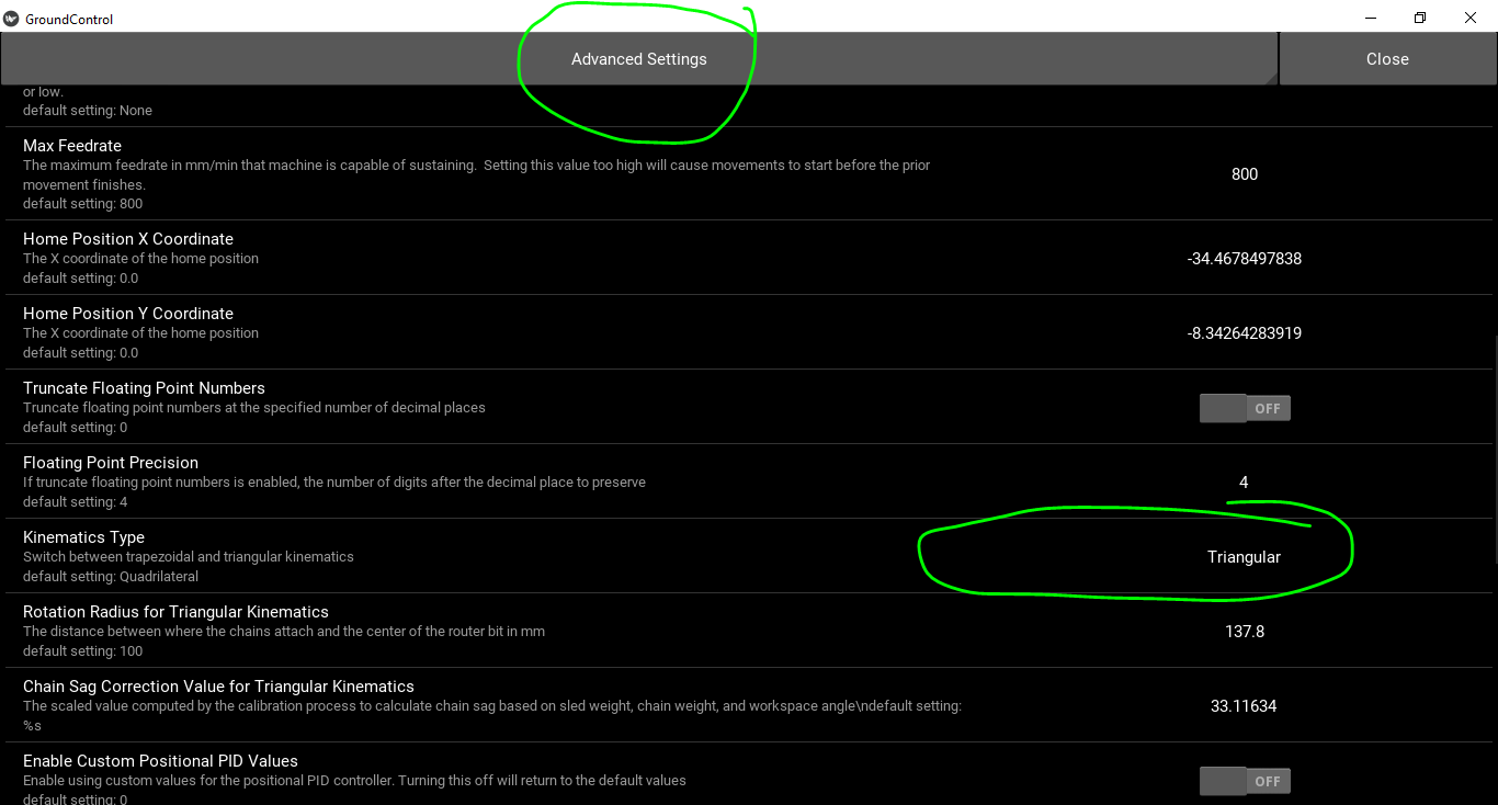
This is the first thing I would look into. If you are some how operating with the wrong math system things are going to be WAY off because the machine is using the wrong system to do the computations. Here’s how you can check. Click the Settings button and then click the drop down at the top to choose Advanced settings. Then check that the kinematics type option is set to Triangular
If you are not using the ring, what are you using? (the original L brackets or one of the triangulation kits)?
@dlang I am using the ring system I just thought I had it set wrong.
@bar thanks for helping me check. It was set correctly to the triangular I was just confused because settings had a option to set the ring radius but I could not find it.
The original benchmark I am sure was good. but just in case, I reran the benchmark. The only thing I changed was I set the chain pitch to 6.37 because I measured over several links and divided to average. Turns out these roller chains have some clearance accumulation in them. This may have not been a good idea as some of the measurements got worse.
Please help me look at data from both benchmarks and find out what I need to change.
BTW the top left square is still distorted, see above pic.
Aaron
masslowcal7162018001.pdf (143.4 KB)
urgent update
I was measuring the squares incorrectly. I was measuring the inside square. Please add 6.35mm to the height and width of the squares on both bench marks. The other measurements are correct.
Aaron
Haven’t heard from anybody in a week just trying to keep this thread going. I have been cutting non-critical stuff out with the Maslow but I want to dial it in. I have some furniture I want to cut out that has interlocking tabs, so I need this to cut to tolerance.
Aaron
It’s tough to give much in the way of guidance without being there to see what is going on. There are so many factors and it’s hard to isolate just one to tweak. A summary update might help to keep things rolling. I’m seeing a score of 9.33 from before which would say that that something is quite off, have things improved from that score?
Hopefully you saw my post above that I was measuring the squares wrong. I was measuring the squares inside to inside. Please add 6.35 mm to each of the square measurements. All else was measured correctly. Is there anywhere I can download that benchmark test spread sheet?
Aaron
Here is the spreadsheet I use for computing the score:
Test Score Spreadsheet.zip (3.4 KB)
If you are still seeing a score larger than 2 or 3 its safe to assume that something is very off. If everything seems normal physically, I would do the calibration process from the beginning without skipping any steps and see if the score improves.
IMHO, the calibration spreadsheet should be integrated into GroundControl at some point in the future.
There should be an entire ‘section’ of GC dedicated to running the machine through its paces, confirming/changing outer bounds of the workspace, calibration and all other diagnostic testing.
just a thought…