I’ve been struggling to get my maslow to draw squares - it is giving me rectangles
Rather than burn through wood I have a pen holder fitted and am drawing on cardboard with it
I have tried the automatic calibration, and a manual measurement calibration and I get the same result.
Drawing a 500x500mm square results in a 502x489mm drawing
Nice right angles, but short on the Y axis by 2.25%
This is fairly consistent between the auto and manual calibration
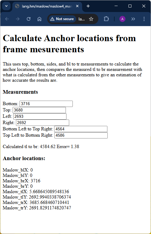
I have a horizontal setup approx 3700x2700mm between anchors
This is the results from @dlang’s fantastic calulator showing the dimensions and a 1mm measurement error in the manual diaganol measurements
keep an eye on it, the error may not be linear, so the scaling may need to
change (either due to position, say near the edge, or due to improvements in
future firmware upgrades)
the x/y scaling is a hack, but that just means it works for at least some
people, even if not the theoretical ‘right’ answer.
I was wondering if anyone has found the x/y scale isn’t working with FW1.11?
I tried to route 4 of 300 x 300mm squares and adjusted the x/y scale after each time before the next route and each time no change to the error, it was exactly the same error x=296 and y=303
I was wondering if anyone has found the x/y scale isn¢t working with FW1.11?
yes, there was a report on that I saw yesterday
I tried to route 4 of 300 x 300mm squares and adjusted the x/y scale after each time before the next route and each time no change to the error, it was exactly the same error x=296 and y=303
note that the maslow error is unlikely to be the same in different places on the
worksheet.
hey @bar are you still expecting to release new firmware that allows x/y scaling? Per my understanding above, scaling doesn’t work in 1.11?
I think I have my router all set up, I’ve been drawing 100mm squares and found that mine is 100.88% bigger that is should be on X axis and 95.77% of what is should be on Y.
In 3d printer land, we’d generally fix this sort of thing by applying a factor to the mm / step for the stepper on a given axis. It can also be done in post processing (slicing) by applying a factor to the generated g-code. It seems most elegant to allow a simple scaling feature as you have done.
You may find that the answer is in the height differences between the anchors and the arms on the machine. I changed the order of the arms by mistake which changed the heights of the arms as recorded in the .yaml file. I started cutting ovals instead of circles. After manually measuring the height differences and changing my .yaml file appropriately the x/y scaling was much better.
Hi, I have a similar problem
Can you write more about how you did that?
Did you just measure the Z distance from the arm belt to the middle of the anchor or did you add the spoilboard and workpiece height as well?
I measured the z height from the arm to the spoil board without a work piece. Then I estimated the height from the spoil board to the anchor. I entered the differences into the yaml file and jogged a square. It was off by .010” over 5”. Not perfect, but good enough for my project. I had to break down the the frame (winter storage), but I planned to “tweak” the yaml heights until I cut a square within .005”
Did you just measure the Z distance from the arm belt to the middle of the
anchor or did you add the spoilboard and workpiece height as well?
The Z offset is the distance from where the belt end is at the arm and
where the belt end is when at the anchor.
The default values are the distances for each arm to the bottom of the sled (so
good if your anchors are at the same height as your wasteboard)
Note that these distances are relative to the plane of the wasteboard/workpiece,
so if it is tilted (like on a sloped driveway) measure based on the slope rather
than based on a level.
so a good way to figure this out is to take a straight-edge or level (ignoring
the bubble) and put it flat on the wasteboard, then extend it out to your anchor
and measure from the bottom of the straight-edge to where the anchor is and
add/subtract that value from the Z offset (note that in v1.16 you will be able
to use the spoilboard thickness if this is something that is constant across all
4 anchors)