X-Y carriage moved by Maslow chain drive

I went through the topics, nothing seemed similar to this question. Several searches also failed … so here goes!

To start with - I have not built a Maslow as yet. I’m still trying to get the Makesmith CNC built … I have no experience and I am not mechanically inclined. But I do work with a bunch of mechanical people and some ideas do rub off :wink: What do I do? I am an electrical engineer, with 25+ years experience in industrial controls. Most of that does not apply to this topic.

Reading through the posts, I like the Maslow design and what you all are doing with it. I think the Maslow method of moving the router is very good, quite accurate. And I like that it can be put together almost anywhere.

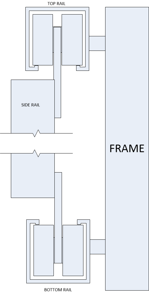
To help with a couple of the sources of error (rotation near edges, wrap on the gear sprockets) I am playing with the idea of using a more traditional-looking CNC frame to support the router. The movement of the router is still controlled by chains from the top corners, and the whole thing is near vertical to keep the chains tight.

The X axis moves on rollers, with the track above and below the work space. The Y axis mounts to a gantry that slides along the X axis and guides the movement of the router to prevent twisting, or rotation. The anchor points on the router base would still be about the same spots, but the router base is connected to the Y gantry so it can’t rotate.

The Z axis would not change.

The bricks would likely not be required since the gantry system is quite heavy to support a decent sized router. The rails would be aluminum square tube, the rollers rubber or plastic with decent bearings. Since the frame would not be used to drive the router movement, the lead screw issues, belts, chains, cables, etc would not apply. it’s still driven by the chains on the corners.

The extra weight of the gantry and the rollers will, of course, reduce the speed of the CNC cuts. It will likely mess up the software to have that much mass in motion, having to decelerate it before moving in a new direction … but I think that is relatively easy to fix compared to the rotation problem.

i don’t think that the gantry needs to deal with the z position since that is already part of the Maslow design. So the gantry can be minimal as long as it is stiff enough to support the router base and router.

If there is an existing topic on this, please move my post. And if not, I’m interested to hear what others see as the pros and cons of this approach.

I’ll start the lists

Pros -
1 - no rotation of the router base, so no location error of the cutting head based on X and Y location relative to drive gear location
2 - no error in the wrap of the drive chain due to rotation of the base
3 - sorry - that’s about all I can come up with for Pros. Is that enough to justify the extra parts, weight, slower movement, etc?

Cons -
1 - much heavier mechanism
2 - higher cost
3 - much more complicated movement of the gantry could bind in some common movement profiles, depending on how the chains clear the gantry and how the chain drive is modified (raised in the Z axis?)

1 Like

@thingstodo

Welcome to our group. I’m still sifting through this post. I’m here to help, we are here to help. I wanted to get a shout out to you someone is looking at this.

Thank you

Thanks @Bee

I’ve been reading through the forums anonymously for maybe a week

OK - the person that will probably be able to answer this the most concisely is @dlang.

I love anyone that is endeavoring to better the project or look for a creative solution. I think the Maslow as is designed is shooting for a specific set of goals. If you want to spend more you can easily get an off the shelf system with more accuracy. I don’t disagree with your observations, they have been addressed in separate parts here in different threads. The issue I see is the complexity and cost involved to implement. It’s the weight of what your proposing that would then need upgraded parts to support it and at that point it almost becomes a different project.

David would be better at outlining the specifics.

Thank you

I’ve posted a couple times about a similar concept and still wonder if it’s feasible (I’m never one for just giving up). As @dlang has said to me, you would be better off switching to COREXY setup if you do a full set of rails. There’s the thought that you couldn’t move the sled smoothly if you put rails on and use the current motors in the corners because there would be a tendency for the rollers/rails to rack because it’s being pulled at an angle. I can see the potential for that to happen.

I did look at using two fixed horizontal unistrut channels (one at top and one at bottom) with unistrut trolleys to suspend two vertical unistrut channels that the sled would ride in (one on the left side of the sled and other on right side of sled). The chains are then only supporting the weight of the sled as the vertical rails are supported by the two horizontal rails (which in turn are fixed to the structure).

To me, the biggest Pro would be that it suspended the sled off the surface. This eliminates tilt and also allows you a great deal of flexibility to do contouring of the workpiece.

For cost, You can get eight unistrut trolleys (two wheel, not four wheel) for $100 off ebay. They’ll work in the superstruts you can buy at Home Depot.

This is just about the most common suggestion that people have.

If you are going to go to all the trouble of building a rail/gantry system, then
dd a few idler sprockets and build a COREXY system.

If you just use the gantry to hold the sled, you are probably going to make
things worse, because the chains will now have to move the gantry as well, and
that will eat up force that gravity applies to the chains.

If you use triangular kinematics, the machine is pretty accurate (and as chain
sag is being added to the calculations, will get more accurate)

Adding a gantry/rail system will do nothing to account for errors in the chain
(the sprocket thing, chain sag, chain stretch, etc), and will do nothing to
account for the problems of cutting fast near the edges (which have to do with
chain angle)

but if you have a gantry, and drive it with COREXY kinematics, you don’t have to
worry about most of these things.

You also have a very different machine than the maslow, and I’ll bet that it
costs you quite a bit more (probably close to double would be my guess, just
from the costs of the rails)

1 Like

1 - no rotation of the router base, so no location error of the cutting head based on X and Y location relative to drive gear location

umm, you are misunderstanding something here. the error relative to te drive
gear loction has nothing to do with rotation of the router base.

rotation of the router base only causes errors if you are using the quad
kinematics, it’s a non-issue with triangular kinematics.

2 - no error in the wrap of the drive chain due to rotation of the base

as long as you still have the chains going from the motors in the corner, you
still have this ‘probelem’ (I put it in quotes, because it’s accounted for in
the software already)

3 - sorry - that¢s about all I can come up with for Pros. Is that enough to justify the extra parts, weight, slower movement, etc?

Cons -

1 - much heavier mechanism
2 - higher cost
3 - much more complicated movement of the gantry could bind in some common movement profiles, depending on how the chains clear the gantry and how the chain drive is modified (raised in the Z axis?)

The resulting machine would be overconstrained, and the gantry would be getting
pulled from odd places, and so would be likely to rack (and therefor bind)

but it’s the cost that is the major issue.

To me, the biggest Pro would be that it suspended the sled off the surface.
This eliminates tilt and also allows you a great deal of flexibility to do
contouring of the workpiece.

This would be the big advantage, you would have a fairly conventional CNC mill,
just tilted on it’s side.

Another con would be that all your sawdust/chips would be hitting your lower
rail, I expect that would cause some ‘interesting’ issues.

For cost, You can get eight unistrut trolleys (two wheel, not four wheel) for $100 off ebay. They’ll work in the superstruts you can buy at Home Depot.

but aren’t they designed to work pulling away from the unistrut? and pulling
straight down?

In this case, gravity is working sideways to your mounts

Thanks for the reply

I searched for your posts and found the thread. Or at least one of them - perhaps there was more.

I had not thought of more flexibility on 3D charging. The tilt, I guess, had not been mentioned much in the posts that I had read.

I had visualized the frame rolling across the work piece in the X axis with a bit less resistance, but more weight, than sliding with the router base. This appears to agree with the posts. Is the issue with the Y axis that it binds when the axis is moved when the chains are not anchored to the middle of the gantry?

Very true… so you need to add a vacuum system to the lower rail! :wink:

They are designed to work pulling away from the unistrut, correct, but if “tensioned” properly, I’d think you could get the bottom wheels to ride on the tracks as well. By “tensioned”, I mean having it so that there’s a little pull between the top wheel and the bottom wheel… sigh… you made me do a drawing…

How practical this all is, how achievable it is, etc… I don’t know. I’m quite happy at the moment with my stock frame (with 2x4x10’ stiffener between motor mounts) and the results it produces. Nevertheless, its a nice thought experiment.

Well, it appears that I know even less than I thought I did. Not much surprise there.

Item 1, the main reason that I was thinking of the frame, appears to have been no problem at all.

Item 2, I apparently missed that it was already accounted for

Well - I guess it’s good that it has only been a thought exercise so far and that I didn’t waste time or money fabricating any of this.

My apologies for questioning a design that I know little about … but thank you for the critique

I like your thinking.

I don’t think where the chain mounts is a problem, I think its that it’s being pulled at an angle… Another drawing time!!

If you use COREXY, you pull the sled left at 90 degrees. Using maslow, as shown in the drawing, you are pulling it at an angle which would tend to cause the two vertical rails to want to rotate. You’d really have to have everything tight to avoid that and I don’t know if it’s achievable without too much friction being added.

1 Like

We just need to create a FAQ that includes this so we don’t have to go over the
answer weekly :slight_smile:

David Lang

1 Like

Perhaps a readme on the search for the forum too? :slight_smile:

But we know you enjoy doing so! :slight_smile:

2 Likes