It’s the same board you get with the M2
The arduino DUE & the new updated Maker Made brand Shield.
It’s the same board you get with the M2
The arduino DUE & the new updated Maker Made brand Shield.
I did notice there that the board info for the Due shield is not up to date.
Thank you for this, I can’t wait to try it.
I finally got a response from Maker Made, they say the Z limits are “not available” or something along those lines.
Maybe we can figure it out despite them?
Yes, but to figure it out you need the schematic, the firmware, and ideally the board layout. We have the firmware only.
If someone traces the lines on the board and produces a list of connections for the pins we are interested in then that would be useful, but it’s extra effort which shouldn’t be necessary. Of course, since there is an Arduino underneath the shield it is perfectly possible to attach a switch to any unused pin and do it that way, but really we don’t want a proliferation of bespoke solutions.
At the very least I’d like to see a description of the shield with the key components listed (basically, the H-bridge chips), and a list of pin functions for the headers on the board. Even if a pin has no function it would be useful to know where is it wired to, what other components are attached to it, and what the intended function was (even if not implemented). All of this can be derived from the schematic, but a Motivated Person could probably do it the hard way if necessary.
Is it this board, which was mentioned at the beginning of the thread?

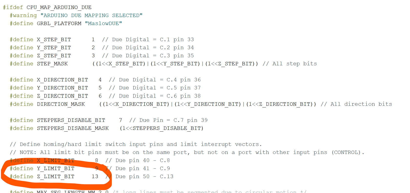
that is the board and according to my (debatable) mad ohming skills, the pins mentioned above are connected. The firmware states that of those pins, 13 is used for the z limit:
It must be enabled in the settings wht $21=1
BUT i also found that if the variable spindle is enabled, it switches it to pin 12, so if this works / when it works, it will only work with the Z+ pins.
EDIT: the heartbeat LED near the USB port is also on pin 13, so the Z+ pins won’t work. I think it might if we change it to pin 17 and use the Z- connection. I’ll add that to the list of things to try.
Here are the default pins for running grbl on an Arduino UNO. The pinout for the Arduino DUE has a base level of compatibility, but the specific choice of pins can be set by the firmware (which then dictates the hardware wiring, or conversely, is dictated by the hardware wiring).
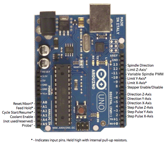
As you have noted, certain combinations cause changes, and certain combinations are incompatible.
For Grbl v0.9 and v1.1+ default builds: Z-limit is on D12 and the spindle enable pin uses the hardware PWM on D11.
For Grbl v0.8 and v0.9+ with variable spindle disabled: Z-limit is on D11 and spindle enable is on D12. This is generally for backward compatibility on older boards.
The DUE should be using the v1.1+ pin allocation by default, but obviously this might have to be altered to match the shield. Hence the need for a schematic…
Hey, nice work!
Just switched over to the DUE board, but I still have my Uno and the old board. So I’m holding one in each hand thinking the old board might be the way to go.
I’m frustrated with Maker made right now because they pushed for the new board for it’s vast improvements.
I copped up the money for the board upgrade and kept my wooden old-school meticulous Z set up. Which works great by the way
So far I’m not impressed with the new board at all.
If CNCJS is indeed compatible with the uno & old maker board, I might just have to switch back.
To be honest I’m at my wits end with this whole thing 
And maker made has told me there’s no way to do a Z limit on the Due board ( DooBoard?). But I don’t believe them. And I don’t want to let them stop us.
Currently the firmware only allows for only 1 Z-hard-limit, if that would even work. Wish you good luck!
Soft limits, set for each job make more sense to me, because a hard limit and a long bit will still allow you to cut into the recessed screw of your spoil-board.
I’ve never trusted the soft limits to be honest.
I have more than enough Z travel. And I have my limit switch installed to trip 1 mm from Max mechanical travel
My spoil board is glued, so no screws to hit!
Well, it’s not actually that simple, but it’s not actually that complicated. I’m pleased to see that the Maslow code has been ported to grbl. grbl is a great choice for operating a CNC machine, and it gives you a lot more flexibility in terms of what you can use to drive it.
I wouldn’t suspect any malice on behalf of Maker Made. I expect that their design works as is, but they don’t want to commit to any development to support limit switches. Even the smallest change is a huge undertaking. Also, publishing information can be fraught, so I can see why they might be reluctant to publish a schematic.
Fortunately, the Maslow grbl code is open and available, and someone with too much time on their hands could sit down and reverse-engineer the schematic from the actual PCB. At that point changes could be made with confidence. Until then it’s all wild speculation and supposition.
Agreed, all well over my capabilities.
So I’m at the mercy of Makermade & all of you damn fine folks 
I appreciate everyone’s time.
If everyone could make their way over to the “Maker Made Users” Facebook page, and promote my poll to add limit switches, maybe we can get some official traction.
I think that’d be pretty darn cool if you all could. Thanks !
-Nolan
I’m not totally sure that’s how it works…
I don’t have Facebook, so I can’t subscribe to the poll. But fundamentally, pressuring someone to do something probably won’t work. The product that you have works, but there is a feature that you want that, as far as I can see, was never promised. To make the change, someone has to spend time and/or money. Where is that going to come from?
Make an issue at the Git (github) of “makerverse” and put “Feature request” in the title.
If enough chime in a discussion will start and it might get done.
The hardware (from my perspective) provides all that’s needed.
The software is up to the developers.
Kind regards, Gero
The feature request part of the maslowdue firmware on github is not enabled, so you cannot make a request other than a pull request to submit changes.
In GC we did that with creating an issue with “Feature request” in the title. New issues can be created.
No sure how welcome that is there though…
the issue section has to exist to do that as well.
I’m really interested in how this all works (but don’t have the skills to program things). I do really want Z axis limit though…
here are my observations:
I don’t believe that the Pin numbers relate to the code that is called in the cpu map, for example on the example above for the UNO @ame showed that the pinouts were on D11 or D12 depending on spindle control, and the code agrees with him, sort of, the exception being that it calls bit “4” to reference pin 12, and bit “3” for digital pin 11 - the physical pin number.
3 and 4 relate to the naming of the pins as control bits under the programming protocol (I think - please shoot me down if wrong). Pin 11 and 12 are called out as PB3 and PB4 - the same holds true for the X and Y limit switches and other coding in the UNO code.
note that in the Due code it refers to 13, but references “Due Pin 50 C.13” I think 13 is the address for the programming bit, not the pin number, the code may actually be watching pin 50.
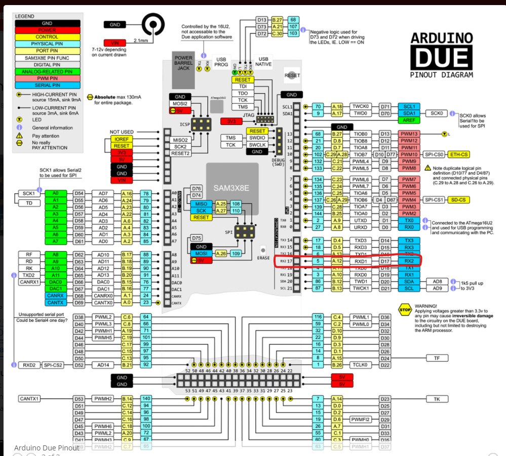
Now if @Orob is correct and physical pin 13 is no use because it is on the LED Bulletin flash channel, but D17 is accessible I suspect the correct bit number is going to be… A.12
Which seems to be a comms channel, this is from the Arduino webpage:
Pin 13 seems to be connected to Z+ and the LED - seems correct
No idea how you would reference pin 17, it can’t be bit “12” as that is probably on pin 51, marked up as C.12, or PC12 on the Arduio site.
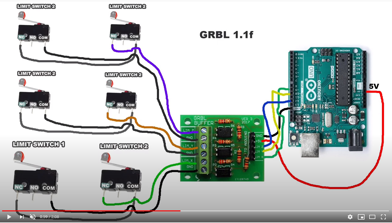
but in everything there must be an answer, given all the above and what is in the current code I suspect the system is watching physical pin 50 for Z-Limit, with 2 switches wired in paralell, one for each end of the z-axis and a resistor/filter of some description inline - like this, but only for the z axis with the wire going to pin 50…
or without the isolation…
this helps… and confirms the UNO connections. v. tempted to try it…