Thanks Roland, I’ll be sure to use counterweights. Do you think it would be worth me going the 14 foot rout if I have the room? And 40” spacing between top cut surface?
I would not recommend it unless you routinely make parts longer than 6’ or routinely cut out an entire 4x8 sheet at once. . Shifting the plywood a couple feet to the left or right gives all the benefits of a bigger machine without becoming a guinea pig for testing.
3 Likes
but if you like testing stuff, go ahead and try it and report back. Would be interesting to hear your experiences.
1 Like
Dlang, I’m willing to try the 14 foot , 40 inch clearance. I’ll probably regret having to spend all that time on the ladder calibrating 12 o’clock position with gears and putting on chains. Do you think it’s worth the time to go 14 feet as opposed to 12 feet if I’m planning on cutting out shapes that are full sheet size for most of projects? Just wondering if think will make much difference in comparison to 12 feet based on the calculations you have provided. Sorry for my ignorance , I’m just not acclimated to some of the calculations other than want min to be high and max to be low ideally. Just trying to decide, as your expertise is much appreciated.
1 Like
Post 12 has a great sheet to compare the forces in the low corners and the top middle.
3 Likes
once you have enough force for the friction and max speeds you use, higher
forces in the corners don’t help
the motors will only support up to ~1200mm/min (at least unless you change the
sprockets)
the losses due to friction are pretty much constant, so going from 3.3 pounds of
available force to 6.4 pounds of available force is MORE than a 200% increase. I
don’t know what friction is, but if it’s 2 pounds, you are going from 1.3 net to
4.4 net, 300% gain
nobody has built a 14’ 40" frame and reported on it’s performance, let alone
compared it to other sizes.
If you can build your machine in a way that you can relocate the top beam and
mount the motors at different distances to do comparisons, you would be doing
the community a huge service and give us data (rather than educated guesses) to
use to answer the next person.
David Lang
1 Like
Thanks David, I will plan for making the motor spacing adjustable and height adjustable as well. Thank you for the insight. These open source communities are a vital resource. I will report back.
I know this is not ideal for everyone but I was thinking about the Mark II. Completely vertical, and having a track that prevents it from moving away from the workpiece as well as towards the workpiece, WE MAY HAVE THIS SOLVED! Thoughts?
1 Like
the track is a fairly significant additional cost and effort to build, if you go
completely vertical, cut pieces can fall out anc cause grief.
I still say that if you are going to go with a frame you should shift to coreXY
and greatly simplify things (eliminating a HUGE number of the accuracy sources,
along with eliminating the need to rely on gravity)
David Lang
1 Like
I am interested in this. How would it look to try and change everything? Remember I’m just a yeoman. Is there anyting about the way the motors move now that would work with this Etch-a-Sketch looking configuration?
The easiest approach would probably be to look at the grbl fork for the maslow
(the one that runs on the Due) and take the motor/encoder drive portion and put
it in the standard grbl that already supports coreXY.
David Lang
I am curious about the relationship between the force exerted on the sled by the left and right motors and the performance and accuracy of the machine.
I’ve been gradually working on upgrading my machine, and one of the big changes is a new, adjustable depth top beam. I almost finished my own Z-Axis when I realized that my frame can’t support it presently. The CG of the sled is too high for the motor mounting brackets I made up originally. So I already need to modify the frame to support the sled. The other factor to the new top beam is that it can be longer than my 112" frame’s current “top beam”.
Which is where I’m going with this long-winded intro. I was playing around with @dlang’s chain geometry spreadsheet and I want to make some sense of the data that I’m looking at.
This is my current, working setup:
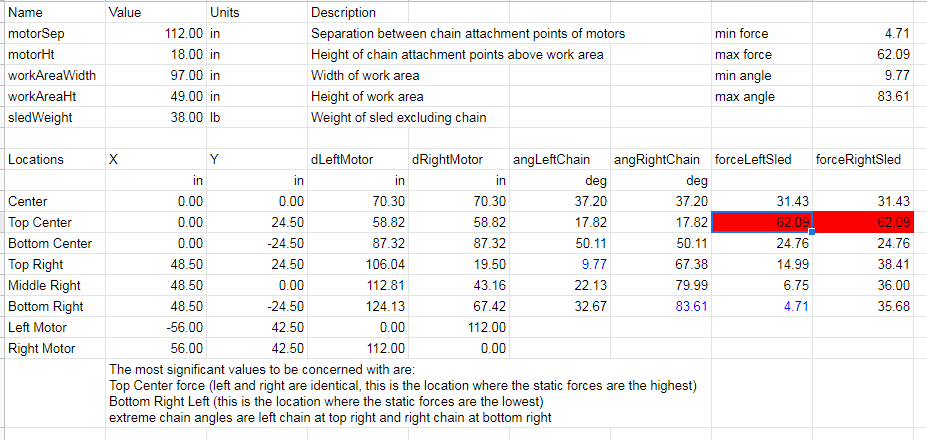
I’ve never stalled my motors trying to move anywhere on the frame, even though the force on the sled at top center is too high for the motors. Admittedly, I determined that the machine only has a usable cutting area that’s roughly 3’ in Y by 4’.
This is the geometery that the new top beam gives me:

The longer top frame reduces this force to 40.7.
After reading through this thread, I learned that the ideal Y offset is somewhere around 30" for a 12’ top beam. In the spirit of experimentation, I changed my current Y offset from 18.5" (determined from CAD) to 30" in the spreadsheet.
The data certainly supports this:

So my question, looking at these numbers, is how much improvement would I see from my current frame’s Y offset of 18.5" to 30"? The force on the sled is nearly half of that on the higher offset. Would that potentially give me accuracy to the top center of a sheet?
It will be a small project to modify the frame to get that 30" offset. But, given that I’m already going to be modifying my frame, now would be the time to do it. And since my frame is steel box tube, I can plasma cut out slots to allow for Y offset adjustment, if I do find that I need to fine tune it.
It’ll then be a fully adjustable top beam 
Thoughts? Am I overthinking this?
1 Like
your sled weight changes from 38 lbs to 20 lbs. Not sure if that is a mistake or if you will be using a new lighter sled. higher top beam gives improved top center performance.
wider motor top beam spacing gives improved bottom corner performance.
Finding a good balance between the two is the trick.
1 Like
if the forces required along the top are too high, a horizontal cut along the
top will tend to droop a bit (and hook up at the end commonly)
if you are trying to accelerate from a stop in the top center, you add to this
the acceleration force, and you end up asking the motors to do a lot.
when the motors can’t produce more power, the system doesn’t catch it well (the
“motors can’t keep up” error was introduced to catch this, but since there is no
acceleration planning, it doesn’t work in practice and ends up being set to such
a large error before it alerts that it’s pretty worthless)
we had a report of someone with a 30 pound sled on a standard dimension frame
and found that they were having problems along the top. one of the examples is
this setup. Based on that, the current recommendation is to try to keep the max
force required lower. We don’t really know where the limits are, I have it go
red at levels about where that 30 pound version would be.
it’s possible that lowering the max force will make it less likely to wear out
the gears (pure speculation)
If you get the max force low enough, you may be able to try different
motors/sprockets and get more speed 
But most of the trouble that we have seen has been in the bottom corners where
the gravity force is the limiting factor. In extreme cases, the sled doesn’t
move while chain is released (slack accumulates) and then the sled jumps,
cutting unevenly, rounding corners, etc.
So, without lots of testing and reports, I focus primarily on increasing the
minimum force, and just check that the max does not get too high.
David Lang
2 Likes
Good eyes. It is intentional. My current setup is certainly heavy. I found when I was calibrating initially, I got much better results from a heavy sled. This is probably mostly because this was before chain sag calculations were in the firmware, so eliminating as much chain sag as possible made it so the machine and the math lined up better. Also, with my shorter top beam, I got much more width out of the cut area with the heavier sled. I never really bothered changing that, given the scope of the upgrades I’m going to be doing relatively soon.
The Meticulous Z-Axis is a much lighter sled overall, and I’m going to see if it runs fine with just the weight of the assembly or if it will need additional weight as well.
Of the two, I would prefer wider over taller. But, of course, getting the full performance over a 4 x 8 would be mint! ![]()
That sounds almost exactly like the type of deviation I was seeing when I was messing around with the max feedrate way back when.
For what it’s worth, my machine was built from a Kickstarter kit. If I remember correctly, the gears where of a higher quality then, but I could be wrong.
It’s almost like you’re reading my mind! ![]() I did get the larger sprockets that you recommended in the thread I linked above. Combine that with the acceleration planning in the Due and I just might stand a chance using 2 flute tooling.
I did get the larger sprockets that you recommended in the thread I linked above. Combine that with the acceleration planning in the Due and I just might stand a chance using 2 flute tooling.
That is especially a problem for my current, shorter top beam. Accuracy drops off pretty quickly outside of the center 4’ part of the bed.
So what you’re saying is that, once again, I’m going back into testing mode? xD
What I am taking away from this is that it would be greatly beneficial to modify my frame to be able to handle up to 30" of Y offset. Maybe even more, depending on the math.
That’s interesting. I hadn’t really taken note of the minimum force before, but that makes a lot of sense. I’ll have to play around with the spreadsheet a little more and see what I can come up with. Do we have a threshold for how high is “too high” for the max force? When the spreadsheet makes the cell red? Are we in the land of speculation, and just not have enough data right now to know that?
we don’t have a lot of information here. I mostly try to make it less than the
stock frame. We currently have the max feed rate set a bit lower than the
machine can move due to problems reported at max speed, and going by reports
that a 30 pound sled had problems, I made it go red about the point that would
be a 30 pound sled on a stock frame.
but it’s a guesstimate, not a hard limit.
David Lang
Apologies for the delay in my response, my weekend got eaten up by a surprise Saturday shift. I haven’t had a chance to look at the forums until now.
I had a feeling that was the case. No worries, I was expecting when I wrote my earlier post that I would need to increase the height of my frame. I should have enough steel tubing on hand to make the risers I will need. I’ll feel a little bad cutting up my frame for it though! >_<
For Funsies, I plugged in the stock frame values (from the old CAD model):

So the number to beat is about 50 (lbs? not sure of the units here). Oddly enough, the minimum force is pretty low on the stock setup as well, although it beats my current setup.
I played around with the numbers for my new setup, and increasing the sled weight certainly helps with minimum force. I’m thinking that this will be my target frame dimensions:

This gives me a good margin in max force over the stock setup. Also, the minimum force is higher than my other hypothetical setups. Looks like I will probably be looking at increasing the sled weight to 30 lbs.
It’s going to take me awhile to get to the point where my machine is back up and running so I can do testing, but I’ll let you know when I get on it. Hopefully there aren’t too many more Saturday shifts in my future so I can focus on my Maslow.
2 Likes
For Funsies, I plugged in the stock frame values (from the old CAD model):
So the number to beat is about 50 (lbs? not sure of the units here). Oddly enough, the minimum force is pretty low on the stock setup as well, although it beats my current setup.
Yes, the stock frame has high max force and very low minimum force. I think I
have it turn red just above 50 pounds force
I played around with the numbers for my new setup, and increasing the sled weight certainly helps with minimum force. I’m thinking that this will be my target frame dimensions:
This gives me a good margin in max force over the stock setup. Also, the minimum force is higher than my other hypothetical setups. Looks like I will probably be looking at increasing the sled weight to 30 lbs.
That looks pretty good. I hadn’t realized how much a higher top beam helps the
max force (by drastically impoving the angles)
I also think we need to experiment with settng the frame closer to vertical.
That will decrease the friction, which will leave more of the force available
to move the sled.
I’m working on getting the maslow at the makerspace running and calibrated well,
at that point I’m going to do testing with different linkage kits and frame
angles.
David Lang
3 Likes
This is something I’m realizing now too. The spreadsheet you wrote up is a fantastic tool for predicting machine performance.
Makes sense. I have a fixed A-frame to support my bed at 15*, so I’m stuck with that angle for now. Depending on what test data comes back with angles, I can always make another A-frame, or even an adjustable one. One step at a time, though. I’ve been using my Maslow pretty regularly lately, so I don’t want it to be out of commission for too long! xD
1 Like
for testing, just put blocks under the back legs to tilt it forward. (that’s
what I’m planning to do)
David Lang
2 Likes