A new way to think about frame size and angle

Hey all,

I took my time to think about the optimum frame size and angle. I think that the optimum can be found, when looking at the cutting force that the maslow can provide at every position of the working area. So I made an analysis of how to calculate this value. See the attachments.

I uploaded an overview of the procedure I am using:
analysis.pdf (539.9 KB)

And the matlab code to calculate the values:
analysis_maslowcnc.m (4.4 KB)

Before I want to do a more thorough analysis, I just wanted to know what you are thinking. If Iā€™m on the right track, or if I missed something?

2 Likes

there is this spreadsheet that lets you try various dimensions, it doesnā€™t account for the frame angle (changes would be welcome)

the force available to the motors is always higher than the force of gravity, unless the force to move exceeds the force available from the motors (depends on real-world variables that you donā€™t know).

so you have two limits

  1. the top center where the limit is how close the force needed comes to the force the motors can apply - friction

  2. the bottom corner where the limit is the force of gravity to swing the sled, which matches the tension on the chain from the far corner - friction

The friction (both static and dynamic) is constant across the work area as long as the chains are parallel to the workpiece (and this ā€˜constantā€™ varies based on the surface itā€™s riding on, including the amount of tear-out from the current cut). Static friction matters because most CAM programs have the sled stop moving when you plunge into the workpiece.

All of the above varies by the frame angle, the closer to vertical, the better the numbers are (lower friction, more gravity available)

but the closer you get to vertical, the less force there is to let you drive the bit into the workpiece (but we donā€™t know how much force is needed, and that will vary on the bit and wood in use)

In the spreadsheet I donā€™t try to figure out the friction and plunge force needed, I just take the ā€˜make these numbers better than stock and your machine will perform betterā€™ approach.

I believe that you come to similar conclusions, with pretty graphs, with a lot more effort, because you map out the entire space and the spreadsheet is just calculating the trouble spots.

There is an earlier tool ( http://lang.hm/maslow/v-plotter.py ) that does a more primitive version of the full map, which helped identify the spots to test.

The real problem is the unknowns that are needed to tie any of these numbers to the real-world

  1. how much friction is there?

    Of the (3.2 pounds-force modified by frame angle) available to move the sled into the bottom corner, how much is lost due to friction?

    The closer to vertical you are, the less friction there will be.

    If friction is 2 pounds of force, then going to a 12ā€™ top beam which gives you 6.4 pounds of force takes you from 1.2 pounds net to 4.4 pounds net, even more dramatic than the doubled number looks.

  2. how much force is needed to plunge into the workpiece?

    As you approach vertical, the available force approaches zero.

without these two values, I donā€™t see how to modify either the spreadsheet you your mathlab work to do anything better than guidance as we canā€™t predict the actual results.

We could find the friction number by having someone with a high-speed camera measuring the acceleration of the sled from gravity (get a well-chewed workpiece, hold the sled with only one chain near the bottom corner, let go and measure itā€™s acceleration)

we can have people try tipping the machine forward while drilling holes and see how close to vertical they can get before the sled starts to rise (try with a fairly dull bit and hard wood)
3 Likes

FWW - If all Maslow CNCs were the same this could be true.

<> All Maslows are created equal

Thank you

2 Likes

I really like the work. What I like most is that it is an attempt to explicitly state the performance attributes (minimum available force) which drive a decision for frame geometry. In order to really get this right, all the potential constraints would have to be considered.

I think @dlang did a good job discussing a number of other potential limiting factors.

It is not clear to me that minimum available force is what constrains the Maslow. Here a few other performance attributes which may be constraining:

  • Stiffness:
    • Stiffness in the bottom corners is limited by chain-sag. If a cutting force is in the same direction of the chainā€™s tension, the chainā€™s tension is reduced; the chain sags more. This leads to a positional error.
    • Stiffness in the top center is limited by the chainā€™s elasticity. If a cutting force is downward, the chains will stretch, which leads to a positional error.

What I like is: if you create a script/model/function which can take the frame geometry as inputs, and calculate these you can quickly analyze a frame design.

My recommendation is to just be as meticulous as is reasonable, to include all the performance attributes and parameters. That way you will be more likely to create something that is broadly applicable.

2 Likes

We have work in place to account for chain sag and stretch (it was developed as
part of the holey calibration work and has been at least partly ported and
merged into the main tree, but there hasnā€™t been a release yet that includes it)

David Lang

So what is the current recommendation? It seems like 12ā€™ distance between motors and 30" above top of work canvas area with a sled of 20-25 lbs and angle of 10-15 degrees is best current compromise? between top center and low corner performance.

3 Likes

That is my recommendation. However, that is not based on the rigorous analysis mentioned in this thread. I actually am not aware of all the historic work that was done to determine the optimal frame-angle. I can say that a 10ā€™ top beam will be limited in the bottom corners of the worksheet. The top-center of the worksheet experiences quite a bit of chain-stretch; the kinematics equations become stiff, which makes calibration difficult. I think the 30" number is very good. Also, the 20-25 lb sled weight is very good.

the real question is will making the frame even bigger say 14ā€™ wide and 40" from top of work piece be even better, but then we start to run into mundane issues like many ceilings are only 8ā€™ tall and 14ā€™ is taking up a lot of room in my garage. The larger the work piece becomes the more ā€œevenā€ the force measurements become over a 4x8ā€™ surface area.

2 Likes

take a look at the spreadsheet (Iā€™m pretty sure itā€™s linked to earlier), try
different parameters.

right now it seems that the 12ā€™ 30" is around the sweet spot for machine
dimensions, as you go wider you have more trouble reaching to the far side, even
as it improves the near side.

There has not been a real test on frame angle and sled weights, this is mostly
ā€œit worked for Bar before he started the kickstarterā€. There have been a few
tests, if you go too close to vertical, to far from vertical, or too heavy on
the sled, we know there are problems

we know that we are closer to the limit in terms of tilting back, 20 degrees
doesnā€™t work while 10 degrees does (the last testing had problems with a 5
degree tilt)

we have not had anyone do any testing since we added chain sag to the
kinematics, so I suspect that we handle lighter sleds and closer to vertical
angles better than we used to. But until someone gets a chance to do some
testing, itā€™s hard to be sure.

David Lang

2 Likes

Yeah. This is a good question. For me, I think that as long as you increase the two dimensions at a similar ratio, youā€™ll end up with an improved machine.

If you just keep increasing the beam-length, youā€™ll eventually run into issues related to the weight of the chain, slow dynamics of the chain, chain-stretch, or frame rigidity. I donā€™t know at what point those issues become prominent, maybe a 20ā€™ top-beam. To my knowledge, nobody has ever made a machine so big that its size became a problem.

I know i should be quiet when the grown-ups are talking. Just canā€™t help it. i know the .py script is just giving rough guidance and after re-framing to 11.5 ft again believe in a ratio in scale of a sheet.

1 Like

so going to 14ā€™ 40" increases the max for by 2.58 pounds and decreases your min force by 1.7 pounds, so itā€™s worse in both places than a 12ā€™ 30" frame

1 Like

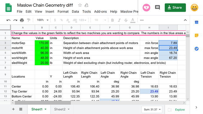
That doesnā€™t make any sense. Something mustā€™ve gone wrong in the comparison.


I put in 170" motor seperation and 40" work piece distance and got about 7.9 and 23.5 for min and max force which is better than stock and better than 144" distance

1 Like

image
In this sample image the green rectangle is about 48x96", the distance between the motors is about double that or 196" and the height from top of rectangle to motors is about 40". Putting those numbers into the spread sheet gives min and max forces of about 10 and 26.5. a difference of about 16. Compare that to the ā€œstockā€ set up which has a difference of about 30.5. the bigger the difference the more variability in the cutting forces.

Building a 16ā€™ wide top beam is really not that hard to do, Most garages are 18 to 20 feet long.

On the other hand most people rarely cut out 8 ā€™ long parts and shifting the plywood towards the center is a lot easier to do.

Iā€™ll point out that the constants in the v-plotter are not reliable, they were tweaked with the assumption that the stock dimensions were good (which we know is not the case now)

the problem isnā€™t the variability in the cutting force, but rather that:

if the peak force needed in the top center is too high, the motors wonā€™t be able to operate there and the sled will fall behind (and droop, producing the ā€˜hookā€™ at the end.

If the minimum force available in the bottom corners is too low, the sled has trouble moving into the corners.

keep in mind that the sprockets on a 10ā€™ beam areā€™t quite 10ā€™ (120") apart they are more like 116"-118" apart

10ā€™ 18" is min 3.3 max 33.7 (stock)
12ā€™ 18" is min 6.4 max 40.2
12ā€™ 30" is min 5.7 max 25.4
14ā€™ 40" is min 7.4 max 22.8
16ā€™ 40" is min 9.3 max 25.5

while garages are 20ā€™ deep, most people donā€™t want to dedicate that much space. They also want a machine thatā€™s short enough to fit through the door (or at least one that fits under the cealing) :slight_smile: we have quite a few people who havenā€™t had space in their workshop for a full 10ā€™ top beam.

40" above the 48" workpiece, which is about 15-18" above the ground for almost 9ā€™ of height. I donā€™t know about you, but I find that rather high to get up to for hooking up chains or measuring if the sprocket is really at 12 oā€™clock :slight_smile: stock doors are 80" high (so you want to stay under 79" tall to clear molding top and bottom)

thatā€™s why I show my work and link to the tools, so others can catch when I make a mistake :slight_smile:

Yes I agree. The point I was making is the ideal frame size is too big for most to be practical.

If Iā€™m looking for best overall accuracy, Iā€™m gathering that right now the sweet spot is a 12ā€™ distance between motors, 30ā€ above top cutting surface, and a 10 degree angle is best? Dlang, thanks for all your insight on forum, it has helped me greatly.

2 Likes

12ā€™ & 30" seems to be a decent compromise with counterweights and not bungees, but not sure if anyone has posted side by side results.