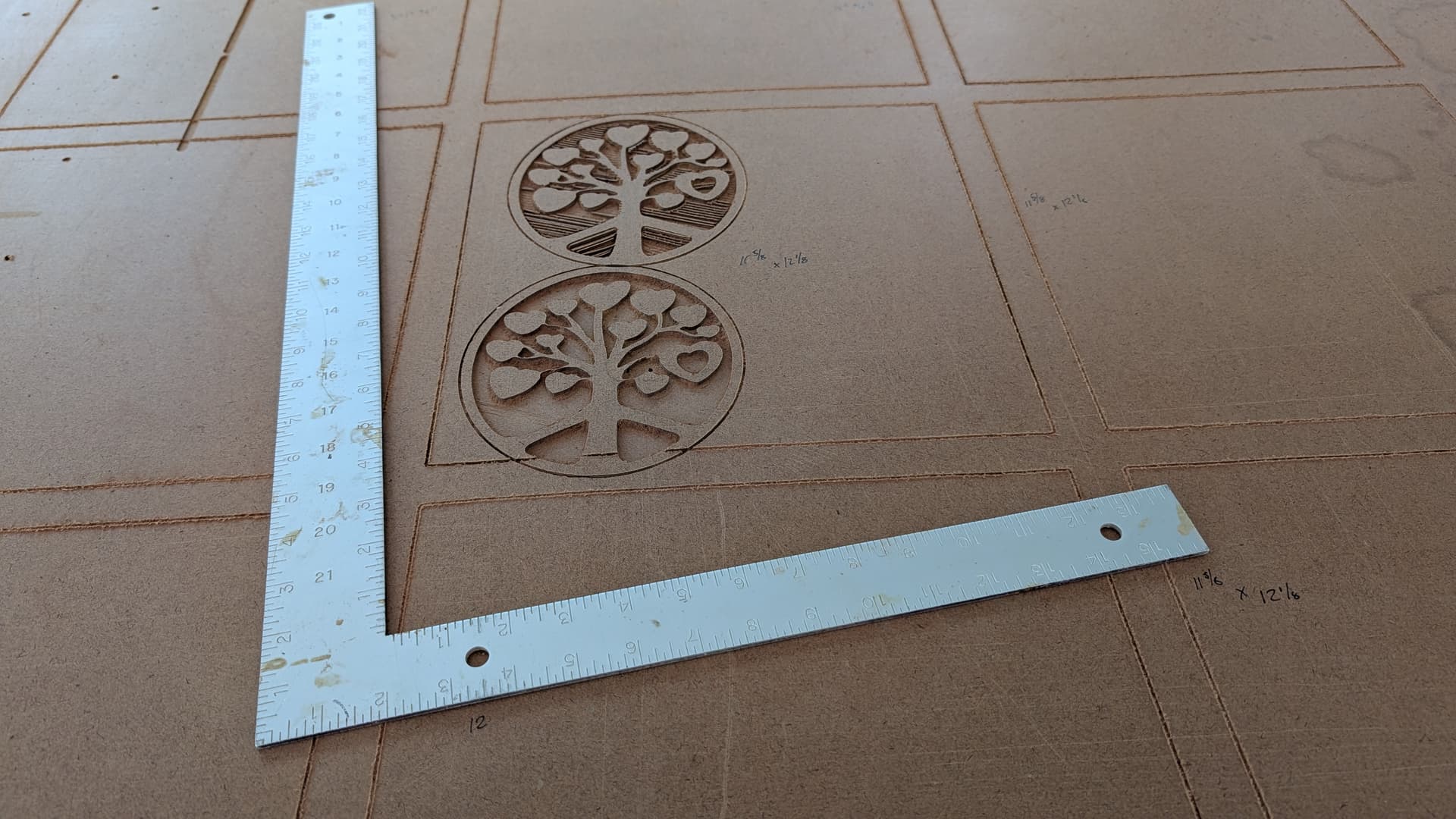
Is there a method now to add a correction coefficient for the X and Y axis, or should I scale this in CAD as previous threads suggested? I made a simple test grid of nine 12"x12" squares separated by an inch boarder in the center of the spoil board. Each was made by re-homing the CNC, and running gcode for a single square. The boxes measure a seemingly constant 11 5/8" (y axis) X 12 1/8" (X axis) on the hourglass frame.. If I can hone this in to around a 1/32" total variation on an axis, things will be close enough for my first projects.
probably best to do this in the CAD right now.
David Lang
1 Like
Any reason on why this is? I have a pretty consistent error on my y axis as well and was just planning on changing the “axes/y/steps_per_mm” to be higher by 1% like ive done on previous gantry style cnc routers. Is there something about the maslow as to why this wont work? I would really prefer not to have to scale in cad
1 Like
I think that it seems like a pretty easy thing to add to the settings. I’ll put it in there for the next version.
Deadset wrote:
Any reason on why this is? I have a pretty consistent error on my y axis as
well and was just planning on changing the “axes/y/steps_per_mm” to be higher
by 1% like ive done on previous gantry style cnc routers. Is there something
about the maslow as to why this wont work? I would really prefer not to have
to scale in cad
the maslow does not have the steps_per_mm setting given it’s very different
kinematics
David Lang
So whats the steps_per_mm setting in the yaml config then if its not that
1 Like
FluidNC requires it to be there, but it’s not used for anything (except for the z-axis which has stepper motors).
Basically every other hobby level CNC router uses stepper motors so the software just expects us to have a value to put there.
1 Like
Ah i see, well yeah if its possible to add that in, that would be a great tool!
1 Like
I should be able to get it in for next week’s update!
2 Likes