The pcb was randomly placed and captured with a web cam. Points from the gcode are linked with the image and the gcode rotated.
1 Like
Using info in this blog:
https://www.pyimagesearch.com/2016/04/04/measuring-distance-between-objects-in-an-image-with-opencv/
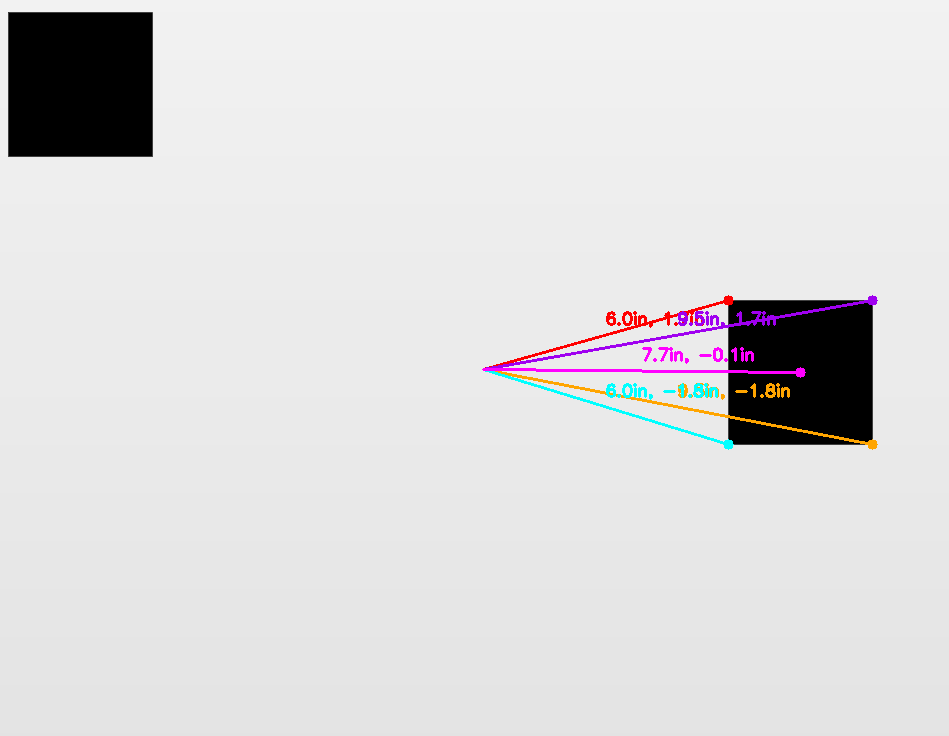
I was able to modify its demo program to calculate offsets from the center of the image. The block square in top left is the calibration image and you tell the program how wide it is (1.5 inches, for example) and the program calculates the distance from the center of the image to the four corners and center of the other square.
1 Like
Are you thinking that you could use a cell phone for a camera? If you could use a cell phone and the Arduino I would think that most people could do this.
The more I think of this the more cumbersome it seems. I don’t have a kit yet but it seems like those who do are not just calibrating once and never doing it again. It seems like a very common and frequent thing to do. Having to take the router out and switch it to a camera and then back to a router seems like enough of a deterrent that I personally wouldn’t want to do this very often. Maybe it’s not a big deal - just sharing some thoughts.
It’s a very cool concept though.
1 Like
I think this is a good project however my vote is to aim at Raspberry Pi3 and the Pi Cam. This is a very usable and attainable standard. I know open CV runs on the Pi.
Just my 2 Cents.
Thank you
The cell phone form factor would make it difficult to fit within the router base. USB web cameras/microscopes are relatively cheap (I got a really powerful one for $30 off amazon).
I understand the sentiment, but in reality, pulling the router body out of the housing is extraordinarily easy to do (at least for the stock router/z-axis setup). So easy, in fact, that I bought a second router and just swap the motors when I need to do a bit change.
Nevertheless, I don’t see that this technique will be universal. For everything I’ve done so far, current calibration techniques works just fine. If you are doing wood carving, like most of what I’ve done to date, then you don’t need to be highly accurate. But if I want to build something with Maslow, then I need a high degree of accuracy. So for such people, this technique may improve their cuts and therefore the quality of their work to a point where things fit together really well.
At the same time, I see a great deal of potential for using this for other purposes in that it can do tests/calibration without requiring you to cut anything or measure anything. As an example, there were some recent changes in software that appears to may be causing problems. What if as part of a QC process, prior to releasing a new version of code, an error map is calculated to make sure the machine is performing correctly. Maybe what I described to date wouldn’t have caught the particular problem that’s occurring, but this technique could be modified such that it would (that’s a topic for another post). Another potential use is that it could also be used to quantify which linkage kit performs the best. It could also be used to quantify how changes in the kinematics calculations affect error… I just see lots of potential uses beyond calibration.
I looked at that but since I want to integrate this into GC and am focusing on just standard webcam type device. There’s no reason this wouldn’t work on a Pi+Cam if that’s something someone was using for GC.
1 Like
There are a good number of after market cameras like from the old playstation at Game Stop for cheap. Like less than $10.
Not sure if that fits a generic camera.
Thank you
It’s important that the camera can focus on a very short distance… matter of inches. So the camera needs a focusing adjustment and a lens system that permits this. Besides that, a USB interface would be best since its pretty universal these days.
The USB microscope I have is apparently fixed magnification of 250x. This is probably too high and something adjustable is likely needed. I’m looking at this one at the moment…
or perhaps an endoscope since they come with long usb cables…
Heck, I am in. I just happened to buy an endoscope from Newfrogg or someplace similar for some inspections.
I agree about it not being that big of a deal to remove the router from the housing. Are you thinking that a person needs to have an adapter in the base so that the camera is centered in the base?
Yes. The key is to be as precise as possible. You want the center of the image captured to be exactly the center of the bit. I’ve been trying to figure out how to build an adapter that is adjustable so you can move the camera left, right, up, down to center it. The more accurate you are with it, the more accurate your measurements will be.
I can think of a couple of ways that you could make it adjustable but it would take more work to make it adjustable in the router. If you had a 3 1/2" round adapter with a larger hole in the middle than the camera and then drill 4 holes in it that meet where the camera is you could use them like pusher set bolts. I have not looked at the base but you might be able to use an allen wrench or make the bolts slotted.
Give me dimensions and I can print a holder.
Thank you
Ideally you would be able to adjust it while it’s installed in the router base… that way you can perfectly align it with a reference point (after you align the router bit to the same reference point)
@marm, post a link to the one you got.
The specs might not have high enough resolution but here is the one from Newfrogg.
Yeah, I was thinking of using a 2 mp camera… nothing like overkill to be safe. But Ive got an old one somewhere in the house that might be 640x480… I can see how it works.
also remember that removing the weight of the router from the sled will affect
chain sag, and therefor position.
good point. I was thinking of trying to build an analog so that it could fit in place of the router (with a notch so the zaxis will work). Basically a tube made of an aluminum sheet wrapped around around with a 3&5/8-inch diameter (why the R22002 has to be odd is beyond me) and a bottom platform that can hold a camera and adjust it’s x,y position. Weight could also be incorporated. Thanks for pointing that out.
I don’t want to overthink it… I guess if you make a body out of aluminum sheet and a bottom out of mdf, it will be pretty well dimensionally stable. So perhaps all you need to do is to create a bottom circle from MDF with an appropriate diameter to fit into the aluminum body (attach it some how), drill a largish hole through the center, make another circle of smaller radius with a hole for the camera to fit through and place it on top of the larger circle, adjust its position, and glue/screw/nail/fasten/whatever it in place once its perfectly centered.

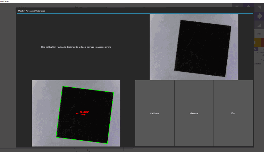
So, it’s possible to measure. The endoscope I have isn’t behaving properly so I used my usb microscope. The square is 0.5 inches. Top right image is a live video feed. bottom left image appears when you calibrate or measure. First you calibrate to determine the scale, then you “move” the camera and when you want to measure the distance offset from the center, you press measure. Exit is supposed to release the camera and exit the routine (I haven’t figured out out to exit the routine… must be something simple)
1 Like
My endoscope is working better now (I think it’s behaving better since I was able to figure out how to do a graceful exit). 640x480 is way more than enough so I think the one you have will work (as long as you got one with a long enough cable). I’m going to work on a mount to install it in the body. Just need to cut some plywood into a stack of rings. I wonder what tool I have that might be able to do that… hmmm… 
1 Like
I have been thinking about this and the best solution is if a person could mount the endoscope in the base, either before mounting the router or with a router adapter, and then have the process automated; if the target was out of range you would have to manually move it to within view and the adjustment would be calculated as well as the offset.
After all my snow removal I will go out in the garage and mess around with making an adapter for my ridgid base and see how it works.