Although I was sceptic that it only put out 9.2V at 255 PWM, the testing results are for me impressive.
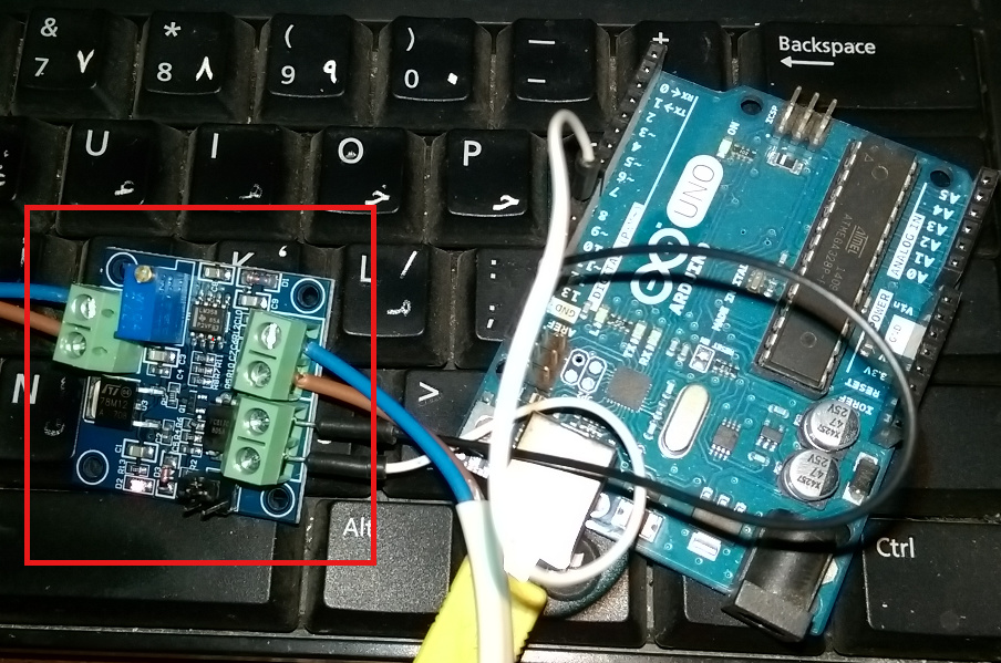
I used an arduino-uno to create the PWM sigal for the module and tested and measured steps.
Further testing:
–> 40 <-- is a cool ‘S-command to PWM-value to spindle-RPM translation number’ for my setup.
This would be the setting/variable to adjust for different hardware.
Increments of 5 in the PWM result in increments of ~200 in the RPM.
But what happens with a S-command not resulting in a integer number for the PWM?
Testing with the aduino uno, putting a value of 102 for the PWM gives me the same RPM as 102.999 does (S4100 would translate to PWM 102.5), so at least on the uno, decimals for PWM seem to be completely ignored.
I could live with that, as 1 PWM difference is 40 RPM difference and I doubt that I would need that precision, but thinking that this might be a more universal pin, other hardware like a servo might require that we round that to the closest integer. Thoughts?
Just posting this here so that others can see what you bought and what it does. I have no affiliation with Banggood other than as a satisfied customer.
Regarding your constant of “40”, this needs to be recorded somewhere, but it is different for different machines. I’m not sure if it should be in Ground Control or the Arduino. Probably the Arduino.
What you could do is store the max rpm of your spindle. Then the maths becomes:
Speed = argument of S command
pwm = speed*255/max
If pwm > 255 then pwm = 255
Analog Write(pwm)
So, if your max speed is 4000rpm and you get S4000:
pwm = 1020000/4000 = 255
If you get S2000
pwm = 510000/4000 = 127.5 -> 127
If you get S6000
pwm = 1530000/4000 = 382.5 -> 255
Having written that I realise your max rpm is 10000, but the calculation is the same.
You could also do the maths by ‘rpm per unit of pwm’, in your case it’s 40. So, get the argument of the S command and divide by 40, capping the result at 255.
But… where to store the max speed for the spindle, or the ‘rpm per unit of pwm’? And how to view it or change it?
I’m not sure I understand your post completely, but will try to answer as far as I can.
Creating a defined PWM pin in the firmware will always have integers from 0-255, no matter what you connect to it. In my case that results to a voltage output for my spindle and is 40 because of the RPM’s I’ve measured.
S-comands in the g-code do stand for spindle speed, but I thought if a variable laser exists, it could also be controlled by the same pin, simply changing that divider/multiplier so the S10000 gives you whatever value you need on the PWM pin. What hardware you connect to it to deal with the PWM is a separate thing.
Update: The potentiometer needs to be removed for full spindle speed control. It ‘kind-of works’ if the knob is not on min or max, but did not bother to measure RPM as I found that removing it gave me full control.
Quoting the Forum warning: The last reply to this topic was over 1 year ago . Your reply will bump the topic to the top of its list and notify anyone previously involved in the conversation.
Sorry for the disturbance, but keeping things together, this post goes here and if it’s only for myself.
RPi, PWM over GPIO for spindle speed control with a PWM to voltage module
Since this is not going into a firmware that runs on the Mega to set spindle speed via g-code and the S-commands, some workaround needs to be found to not set speed via a potentiometer, but remote.
Current stage is via ssh terminal to the RPI, to set a duty cycle for the PWM with python script and user input. Infrared module shipped and on the way to make this buttons pressed.
Spindle PRM of 20,000 in my case is broken down to 100 steps, so 200 RPM more per 1% duty cycle.
Code:
Note that on a RPi 3B+ my pin 40 has ~ 1V at boot. Using the GPIO.cleanup() exiting the script also sets the pin to 1V. To combine a relay that can be triggered with the Holey Firmware would be a cleaner option then my approach, but not waiting a month or more to get one.
Exiting the scrip is not clean, as running it again would trigger a warning that the pin is already in use.
GPIO.setwarnings(False) suppresses that warning.
To get pin 40 low (~0V) at boot edit the /etc/rc.local" and add “pigs modes 21 w” before the “exit 0”
Note that the pin number is in BCM, not BOARD, so my board pin 40 is addressed here as 21.
RPi boot with 0V at pin 40.
Wondering if Webcontrol or Makerverse can fish the S-command out of g-code to trigger this on a not firmware level.
Edit: After further testing a normally open relay seems mandatory. The editing of /etc/rc.local is not sufficient. The pin is for ~ 30 sec still at 1V during boot. This happens on a hardware level that can not be solved without a relay to cut the spindle power until boot has finished.
I’m not sure if i understand you correctly. I have the arduino mega and the TLE5206 motor-shield with 3 PWM pins i could use. So adding a PWM function based on the S-command in g-code to the firmware was my first hope. Now with using either Webcontrol or Makerverse on an RPi i see the chance to get spindle-speed from without having to add it to the firmware using the GPIO.
Wouldn’t using a new controller involve porting the control of DC-motors and a the kinematics of the Maslow require to write a new firmware from the scratch?
I thought that the Maker Made DUE shield and firmware was based on grbl. In other words, the Maslow kinematics have already been ported to the grbl codebase. Unless I have misunderstood something?
Yes, the Due shield. The only source for that comes with a Due and a case. I have a Due and don’t want the case. The reason i’m not buying, because i can’t justify the beefy price to get 3 parts, where i only need 1. So for now i’m stuck with the mega.
The Due firmware has indeed the spindle speed control. The Spindle widget is also in Makerverse. It definitely would be the better option.