Hi all. First post here. I am running a brand new Maslow 4.1, using a vertical 8x10 frame, with a 4’x4’ workpiece.
I have been able to calibrate successfully and make several cuts that look great and are very consistent but are “skewed” a bit long in the x direction and short in the y direction. I’ve attached a picture of the parts, which are supposed to be circles!
My lower circle was off by +3.5% in x axis and -4.5% in the y axis.
My upper circle was off by the same in the x-axis but -3.2% in the y axis.
The right angles on that rectangle are also bang-on square compared to themselves and to the base of the plywood. There was some wonkiness along the top edge but based on the frame size checker, that should be expected.
What should my next troubleshooting steps be? I’ve heard talk of manual calibration being better but couldn’t find much info on how to perform that process on the newer Maslow. Could there be other confounding factors?
I would start by just running the vanilla calibration process again. It should take the results from before as a starting point and improve on them hopefully giving you better results.
You can also in the settings manually correct for some X and Y scaling, but this seems too far off for that yet.
Manual calibration just means measuring the exact coordinates of your anchor points by hand and entering them in the settings. Some folks have reported great results doing that, but I haven’t personally had it work well (I guess I’m just bad a measuring )
@gwhitaker did you get your issue resolved? If so curious what you found/did. @bar I am having this exact same problem, and wondering next troubleshooting steps as well.(I have run calibration three times)
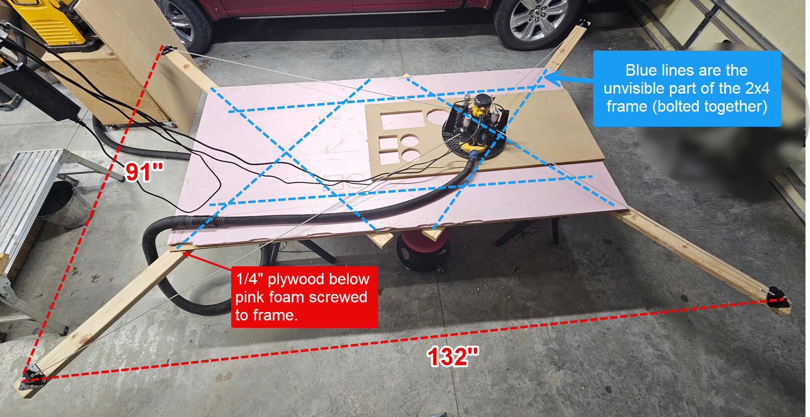
My frame is made out of 2x4" lumber bolted together with a 1/4" plywood screwed at corners. The mount pins are 91"Tall and 132"wide. Then a piece of 4’x8’ pink foam as sacrificial layer. It’s not without flex, but the flex is not in direction that the belts really pull. It’s seems quite stiff in those directions.
I have calibrated three times and still not getting Round circles or Square squares.
Here are my test cuts and results (in Inches):
Calibration
Shape
X (Width)
X (Width)
Y (Height)
Y (Height)
X%
Y%
Intended
Actual
Intended
Actual
First Calibration
Circle 1
6
6.1875
6
5.5625
3.1%
-7.3%
First Calibration
Square 1
10
10.375
6
5.5625
3.8%
-7.3%
Second Calibration
Circle 2
4
4.125
4
3.75
3.1%
-6.3%
Second Calibration
Square 2
4
4.125
4
3.75
3.1%
-6.3%
Third (Current)Calibration
Circle 3
4
4.09375
4
3.78125
2.3%
-5.5%
Third (Current)Calibration
Square 3
4
4.09375
4
3.78125
2.3%
-5.5%
Things got a bit better after the third calibration, but still off way too much to do anything with the machine. And that might be because I did this test a bit more in the center of the frame. The first two cuts were a little bit lower and to the left, but still well within the “green area” of cutting.
I also included the last Serial output from the most recent calibration & current maslow.yaml file in case that helps with any diagnosis. Maslow-serial (19Jul2025-AfterCalibration).log (45.8 KB)
hi,
from a quick look, your frame dimensions are quite a bit off from the 132" you are announcing.
What worked for me regarding dimensional accuracies was to measure everything by hand (even diagonals) and calculate the appropriate coordinates accordingly, with BL(0;0). If you don’t know a software to do so, you can try with chatgpt
What worked for me regarding dimensional accuracies was to measure everything
by hand (even diagonals) and calculate the appropriate coordinates
accordingly, with BL(0;0). If you don’t know a software to do so, you can try
with chatgpt
here is one you can use (you will need to rotate things to read the text
I do still think that could be a concern. The frame flex test is done right in the middle which like you said will be the direction the arms have the least flex.
Have you tried entering manual measurements for the anchor points locations? Some folks have reported good luck with that
@dlang & @bar
If I understand the process for manually entering. I first need to take the measurements of the belt anchor pin points, Top, Bottom, Left, Right & Diagonals. Can you confirm that those measurements should be center to center at each anchor pin point.
Then take that info and run through that calculator in the other thread that is linked above. If that is correct, then that is what I did and got the following results. Which if I understand that error may be too high, as it should be close to zero. And if it’s too high then that means I measured or entered something wrong?
I double checked my measurements and measuring to 1/16" accuracy at this point, I get the following from the calculator.
Then I did all that and rebooted the Maslow4.1, then did a retract all, then extend all, pined the anchors, but after pressing tension id did tighted the belts, but it would not let me move the device. It said the Maslow was not ready.
If I understand the calculations, is my issue that the -27.98 error is too large? That should be closer to zero ±4ish?
If I understand the process for manually entering. I first need to take the measurements of the belt anchor pin points, Top, Bottom, Left, Right & Diagonals. Can you confirm that those measurements should be center to center at each anchor pin point.
they can be center-to-center, of left edge to left edge, or right edge to right
edge.
just not left edge to right edge
it’s sometimes hard to determine the center accurately, so edge to edge is
frequently easier to do.
you can even put a hex bolt in and go edge to edge of the hex bolt, just as long
as you use the same edge.
If I understand the calculations, is my issue that the -27.98 error is too
large? That should be closer to zero ±4ish?
yes, this error is far too large, it should be <1mm ideally.
this is in here to catch the situation where you mess up the measurements.