Intersting insight into anchor point math

I have been looking into how we can improve the math to locate the anchor points and I had a new thought.

We have five variables that we can adjust. The bottom left anchor point is declared to be (0,0) and the bottom right anchor point is at y=0. Those are freebies because we get to define the coordinate system.

That leaves us with top left x,y top right x,y and bottom right y to adjust which is five variables. We then also have the fitness for each possible combination of points which is a sixth variable.

I’ve been struggling with how to visualize that space because we humans can’t really visualize six dimensional space super well.

Today I had an insight. Our frames are mostly roughly rectangular.

What if instead of trying to visualize something in 6 dimensional space, instead we pretend that the frame is rectangular. That gives us a 3D space to explore (width, height, fitness).

It’s not exactly right, but it does help to explore the space.

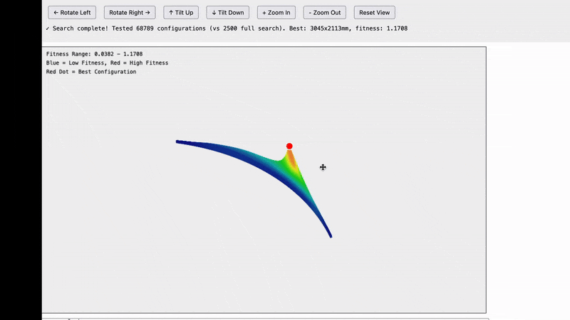
Here are the results and they are quite interesting.

ezgif.com-optimize

Note that this is not a graph of the machine itself. What we are looking at is possible frame widths on the X axis and possible frame heights on the Y axis and the fitness score for how well that frame size matches our data in the Z-axis. For example the bottom left tile is for a frame of size 100x100mm, the tile one to the right from that is for a frame of 200mmx100mm…the top right tile is for a frame that is 5,000x5,000mm.

The insight we’re getting here is that all of the possible frames which reasonably match our data seem to fall on an arc centered around 0,0.

I’m not sure exactly what this means, but it does dramatically reduce the search space that we need to explore.

I’m going to keep investigating

I’m puzzled, where is the Z axis coming into play?

I don’t think our frames are close enough to rectangular to be able to ignore the difference, but it may help visualize things.

1 Like

The z-axis of the machine isn’t involved, the z-axis on the graph is the fitness of each point.

The goal here isn’t to solve the actual frame dimensions (because we know those aren’t rectangular), the goal is to find the best starting value to for the system to converge quickly to the right answer. Basically a first approximation pass.

Also the goal is to just try to understand the problem space better

fun detail. I was writing up a prompt to throw at AI (including seeing if it can
do a 3d solve to find the Z offsets) and in it’s analysis of the problem, Grok
called out the Maslow CNC as an example of the problem being solved.

David Lang

1 Like

Knowing that we can limit the search to just around that arc (it does appear to be a circle) allowed me to increase the resolution without needing to wait years for it to compute.

There does seem to be a clear maximum at the correct frame size, but the data is quite noisy so we can’t simply walk the curve until we find a local maximum

ezgif.com-optimize(1)

OK I have some more good news. I optimized the system to the point that it can handle higher resolution sampling and the noise went away

ezgif.com-optimize(3)

It looks like the good points fall on a really narrow line along the arc and the noise that we were seeing was coming from quantization (basically any time one of our grid sample points happened to land close to the circle.

Interestingly I played around with plugging in a larger data set and that seems to widen out the circle which is neat, but not really that important for us since the goal here is just to get a better initial guess before we begin using the genetic algorithm to refine our results.

ezgif.com-optimize(2)

1 Like

I would also suggest expanding the 6 point rectangle we currently use to a 3x3
grid.

in theory, 3-5 points is enough to find the anchors, but the exra 150mm in
height and extra data points will go a long way towards more accuracy in the
initial estimate

David Lang

1 Like

@bar - checking my understanding of your visualisations - is this fitness-for-a-given-frame-and-set-of-belt-measurements (Z) against X/Y where each X/Y is a theoretical X/Y length/height for a possible (assumed rectangle) frame that we think those belt measurements in Z could correspond to?

I guess my real question is - is this on one set of calibration data, or have you tried it on a few different shapes / sizes?

This is exactly correct :grinning_face:

I tried it on a few different shapes and sizes and the pattern seems remarkably consistent

1 Like

Yeah, my guess would be that the arc would scale with different frames or possibly get fatter the more flex is in the system, but that’s just a guess.

My intuition is:

  • It’s an arc is because the same belt lengths can trade X for Y (ie the same belt lengths could be the actual frame size, or one that’s smaller on X but larger on Y).
  • But having multiple spaced out sample points is what gives you the Maxima for fitness.
  • The flex / stretch / etc in the system is what stops it being just a point.

But that’s purely speculation.

Again speculatively - something I felt would help when I last had time to look at calibration would be stratified sampling for the locations of the points, not a grid (so instead of being at 10cm spacing exactly, they are random location up to ±5cm of that grid point for example. We might be at a point where that’s nearly feasible to test too.

Would be interesting to:

  • Compare the plots for the same frame but different grid sizes and see what the difference.
  • Do a stratified sampling grid as above and see if that makes a tighter arc or not
1 Like

My hunch for why it looks like a circle is that for a single set of measurements all of the possible frame sizes seem to approximate a circle.

ezgif.com-optimize(5)

I’m not sure what that would look like when we add more measurements (in theory it should be a point), but I guess that points along the circle still appear “less wrong”

2 Likes

That is a very good visualisation of what I was trying to say! :joy:

I’d imagine that if you plot that movement for one of the other point’s belt lengths, then where the two arcs overlap would be the fitness Maxima…

It’s interesting that in a round about way you’ve arrived at a sampling algorithm - you’re doing a simplified grid sampling rather than picking random points in the space, but still it is a sampling algorithm!

1 Like