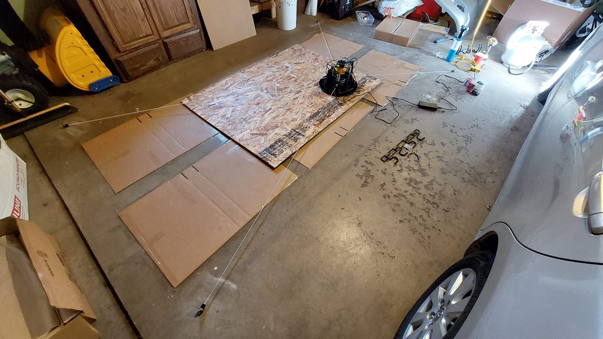
After building, anchoring, and updating firmware, I ran the calibration as described in the user guide (retract, extend, etc.). I don’t have the logs, but I think it was something like 0.1 fitness. Ran it a couple more times with no better results. During some (but not all) of the measurement points, one belt was slack, so maybe that caused issues.
Tried to make it more accurate by carefully measuring the distance between anchor points, solving them in OnShape, and putting the resulting coordinates into maslow.yaml
I reduced the calibration space to a 4x4 grid in a smaller area (like 1000mmx800m). The fitness was poor again, like <0.1.
I reduced the calibration space further to a 2x2 grid in 800x800mm. I ran that calibration 3 times, changing nothing between the runs. I got these fitness levels in chronologic order: 0.074.txt 0.122.txt 0.379.txt
I supposed the 0.379 might be good enough to set those values as new guesses for future calibrations (but not good enough to run with), so I changed to those points
(maslow.yaml) and ran another calibration. Results were poor yet again (0.033).
Your ‘frame’ is very narrow (6.53 x 10.7 ft for us in the US) - I’m pretty sure the arms are running out of travel and the belts are not straight as a result. Could this explain the poor calibration?
If you are using 1220x2440mm plywood then with a frame that is 3267x4374 (10.7 x 14.4 ft) you can reach all points without hitting the arms but the Maslow will have to rotate the body a little in the corners (about 3°), see my diagram attached below.
If you enlarged your frame to these dimensions you would have to extend 4079mm (13.38 ft) of belt, which just fits within the 13.5 or 14.5 ft of belt (I hear different numbers).
The frame could be made smaller if you could accept more rotation in the corners, see the second diagram attached. In this case the frame would be 3324x2430mm (10.9 x 7.97 ft) and at the centers of the sides there would just barely be no interference with the arms. In the corners there would be no interference with the arms but the Maslow would have to rotate 8°. The belt length would be about 3411mm (11.2 ft). I think this is the smallest frame you could have without the arms interfering.
I know this isn’t my post you replied to but this was my concern, not being able to get to all edges accurately… My frame is gonnq be 3700x2700. I’m hoping this would be enough to get all my 2440x1220 . Do you think that would work please? Good knows how you’ve worked all this out:rofl:
I’m getting faster at it :-). I’m stuck at my desk nursing an infection in my knee replacement so there is not much to do except obsess over frame dimensions. At least I’ll know what I want to do when I build mine after practicing on everyone else’s issues. I should just make a spreadsheet.
Your frame dimensions look fine. The Maslow won’t have to rotate in the center area of the two sides but will have to rotate about 6° in the corners. You could reduce that if you made your frame bigger - I don’t know how much of a difference that makes. I suspect it is more important for a vertical frame where the weight of the vacuum hose and power cord may want to pull the Maslow into a certain orientation, most likely vertical, but it depends how the hose and cords drape.
Hi! in another thread I was trying this same thing. except for the rotating angles, I hadn’t reached that yet.
Your top drawing I agree with, I get the same result, sizewise
but the bottom drawing I think is not correct. I found that the minimum angle of two opposite arms should be at a minimum of 130 degrees, otherwise the arms will collide with the uprights.
I found that the lowest frame with no collisions has to be 2855 high and 4492 wide. Here is my simple sketch:
So this is interesting as if you therefore know the min angle at the centre of the workpiece (ie 1/2Wx) and know the max distance of the workpiece height (or Wy) and that the angle has to be more than 50° between arms (yes…?) at 1//Wy then there is a ratio / formula that should show what will work for the frame and what won’t …?
It’s currently 2:1 for work piece (8x4) so would logically extrapolate that as a rectangle, a calculated ratio should suffice but I’m not sure if this is what @dlang and others are trying to work out with their calculations …?
So this is interesting as if you therefore know the min angle at the centre of the workpiece (ie 1/2Wx) and know the max distance of the workpiece height (or Wy) and that the angle has to be more than 50° between arms (yes…?) at 1//Wy then there is a ratio / formula that should show what will work for the frame and what won¢t …?
It¢s currently 2:1 for work piece (8x4) so would logically extrapolate that as a rectangle, a calculated ratio should suffice but I¢m not sure if this is what @dlang and others are trying to work out with their calculations …?
that’s where we started, but we found it wasn’t that simple.
one constraint is the maximum angle between adjacent anchors (140 degrees)
but then we found that there is also a minimum angle between opposite anchors
(130 degrees). This ends up being the biggest limitation
and then the constraint of belt length no more than 14.5 ft (only comes into
play with very large frames and workpieces)
that’s what the spreadsheet is checking as you enter frame and workpiece
dimensions it checks the angle and turns a cell red if the angle is out of
bounds
You can trade off height for width. But yes, it does seem that to cover a full
sheet of plywood you are unlikely to be able to use the stock frame.
note that when the arm hits, it doesn’t mean that the machine becomes worthless,
it starts off just being less accurate at the left/right edges and/or corners
(we still need to plot this out to show the shape of the problem)
only if you go well past this point will you run into real problems.
Where that ratio comes from I don’t know. I looked at the angles the arms were able to rotate (50 degrees each, and a dead zone of 40 degrees between the 50degree zones) and put that and the workarea and frame in a parametric sketch in CAD. David Lang did the same thing but with math in a spreadsheet. Results are now the same.
If the frame is smaller than ideal, there will be zones on the workarea where the accuracy is off, but I haven’t looked into by how much that would be, it might be oke? And it might be possible to make a workaround in the software .
I didn’t observe any of the arms running out of travel, at least not to the point of making a bend in the belt like you’re saying. Even if they do run out of travel, I’d expect that it’ll just rotate the body a little like you mentioned rather than making a bend. I’m not against enlargening the frame, but it seems overkill to me when the reference frame is something like 8ftx10ft and I’m pretty close to that.
I also would have thought that reducing the calibration size to 800x800mm would get rid of any of those issues and allow it to converge on a solution. If you have time could you rerun your calculations with frame size 2000x3000mm and working area 800x800mm, I’d be curious to see the result.
When I take a video, we’ll see for sure. Stay tuned!
Ok so I’ve been playing with the numbers and when I amend the offsets and more importantly make the Y offset larger than the X offset, I get to a smaller frame…
I’d need to validate it with someone else but I think if you start to correlate workspace X:Y as a 2:1 ratio, using a 4:3 ratio on the Y:X offset reduces the space required when you add a small additional common offset.
I’ll upload my spreadsheet later (@dlang based on yours so some of the calcs I have left alone …!)


