I’ve not seen the Maslow 4 schematic yet. Q: What IO is drawn out to through-holes for pin headers - I2C, SDIO, 3v3 TX/RX, GPIO, PWM, etc. ? These IO will be important for the community to enhance the firmware & their Maslow’s features.
I2C (with power)
allows for an 2x16 LCD or OLED screen 32x128 or 64x128 to glance at it for progress without looking at the WebUI
allows for sensors (temperature, motion) and other digital IO to be added to
3v3 Tx/Rx - all development work needs a native serial console
SDIO - this will allow folks to add their own SD Card breakout boards for additional storage & features.
for possible user mods
logging
various file storage
Some GPIO, kind of necessary for things such as having an I2C sensor needing to switch/latch on-off a relay or optoisolator – such as sensing & turning a cooling fan on.
PWM - I suspect those are all used up by the motor controller.
I know it’s late in the game to add parts, it also adds cost for features some folks won’t use. Do not add them as it will create delays.
But please consider adding at least adding the traces & through-holes to allow others to enhance their Maslow 4’s. The headers do not even need to be in straight line like on an SBC - spread them around to where it’s convenient & workable for the current board layout.
Thanks for your consideration. Cheers.
(I’ll post a short version referencing this post in my KS Pledge).
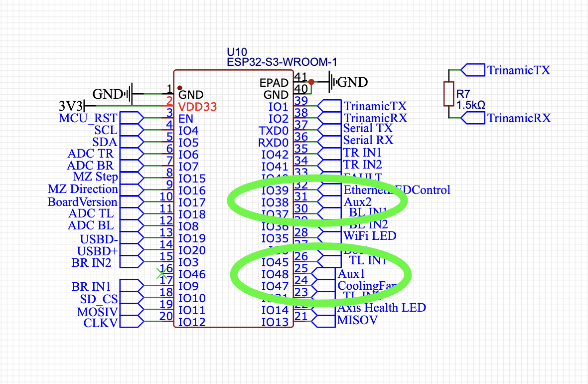
There is already an AUX connector on the board…It’s a JST-XH connector, but those have the same pin spacing as a header if you want to connect that way, they’re just a little more secure…right now it has 3.3v, GND, Serial TX/RX and I believe we will have two extra GPIO pins, but it’s possible that there will be four. I will be sure to break out any unused GPIO for expansion.
I agree that it’s super important to have as many as possible.
Something else just crossed my mind – more spaghetti ideas to see what sticks. Please don’t waste your time if it has a dead end or a major time sink.
I just remembered that ESP32 has built-in CAN Bus two-wire (as mentioned here on this Reddit post).
Would it be possible to break those out as well? IIRC, some other CNC machines also use CAN Bus - just like some Klipper 3D printers. Having CAN through-holes broken out would likely benefit the future use-case of Modders.
a laser on an open frame like the maslow is fairly risky. people have done it in
the past, but I think they did it for just cutting (due to the low speed of the
maslow)
I don’t know Bar’s plans, but I would not expect it.
I made sure that the controller board will support it, but @dlang is right that I think it’s a little too dangerous so I probably won’t make an official one. I am 100% certain that there will be Maslow style laser cutters available soon.
I think that Cubiio might be one of the first to bring one to market. They do lasers AND have a CNC very similar to Maslow4 so they’re in the running for sure. I think that there is probably a way to do it safely, but it’s not on my agenda to try
Pin to pin spacing on JST-XH is 2.5 mm, as opposed to 2.54 mm (.1 in) for a standard header. For two pins you might make it work, but not for three or more pins. See update below.
tyvm for the pics. super helpful. After some light cross referencing this morning, it appears this ESP32-S3 isn’t built with leads for i2c, sdio, etc. - just gpio, usb, serial, spi for psram only, etc. It appear specifically built for projects the RTC potential and heavy GPIO.
Too bad Espressif didn’t include i2c as it would have allows for all sorts of feedback sensors, displays, triggers, and more off two pins vs possibly sacrificing gpio for detection. Then again, i2c would need polling where gpio could have faster detection (important for heavy equipment.)
Given we’ve only two GPIO, besides UART, I wonder what folks will come up with. I’ve not dug into FluidNC to see what they could be best served as for the Maslow4 use-cases. Guess Darwin’s “survival of the fittest” will determine that. XD