I was thinking of making some sort of movable mount to mount the motors on to be able to set the distance of the gear in or out to make the chains parallel with the material so that after I got the linkage set on the sled in the best place for the CG I would not have to change the mounting point on the sled for different material thicknesses.

glad I asked, that is a lot simpler than I was thinking
1 Like
A carriage bolt with the square part sized to your slot would allow you to only need to access these adjustment points from the bottom (wouldn’t need a wrench on top). Although you probably want these pretty tight so the motor board couldn’t twist on you when cutting up high.

now I am on the path of just adding more metal to the motor mount or making a new one that incorporates the 1/4" slots in the bottom.
How much travel do you think you will need? I am banking on being able to use the slots in the motor mount to account for material thickness if needed. Of course, my motors are mounted on the opposite side of the mount the same way as @mrfugu. Mine doesn’t allow for easy adjusting underneath at the moment, but the slots do allow for about an inch of movement.

2 Likes
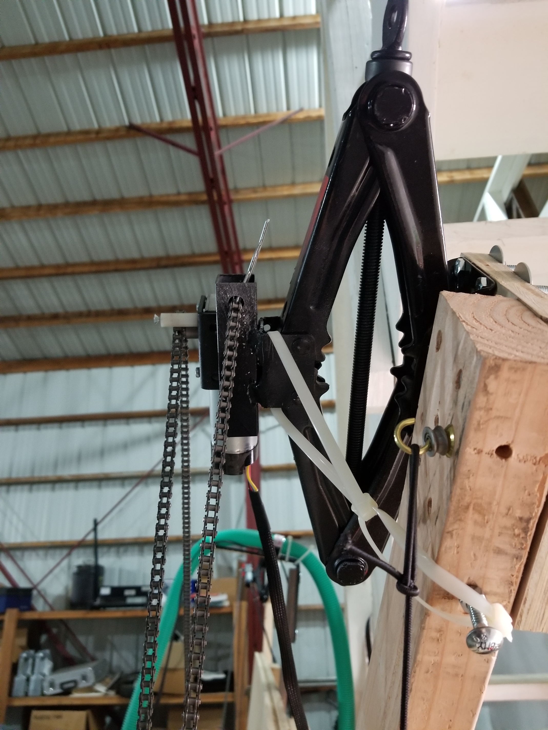
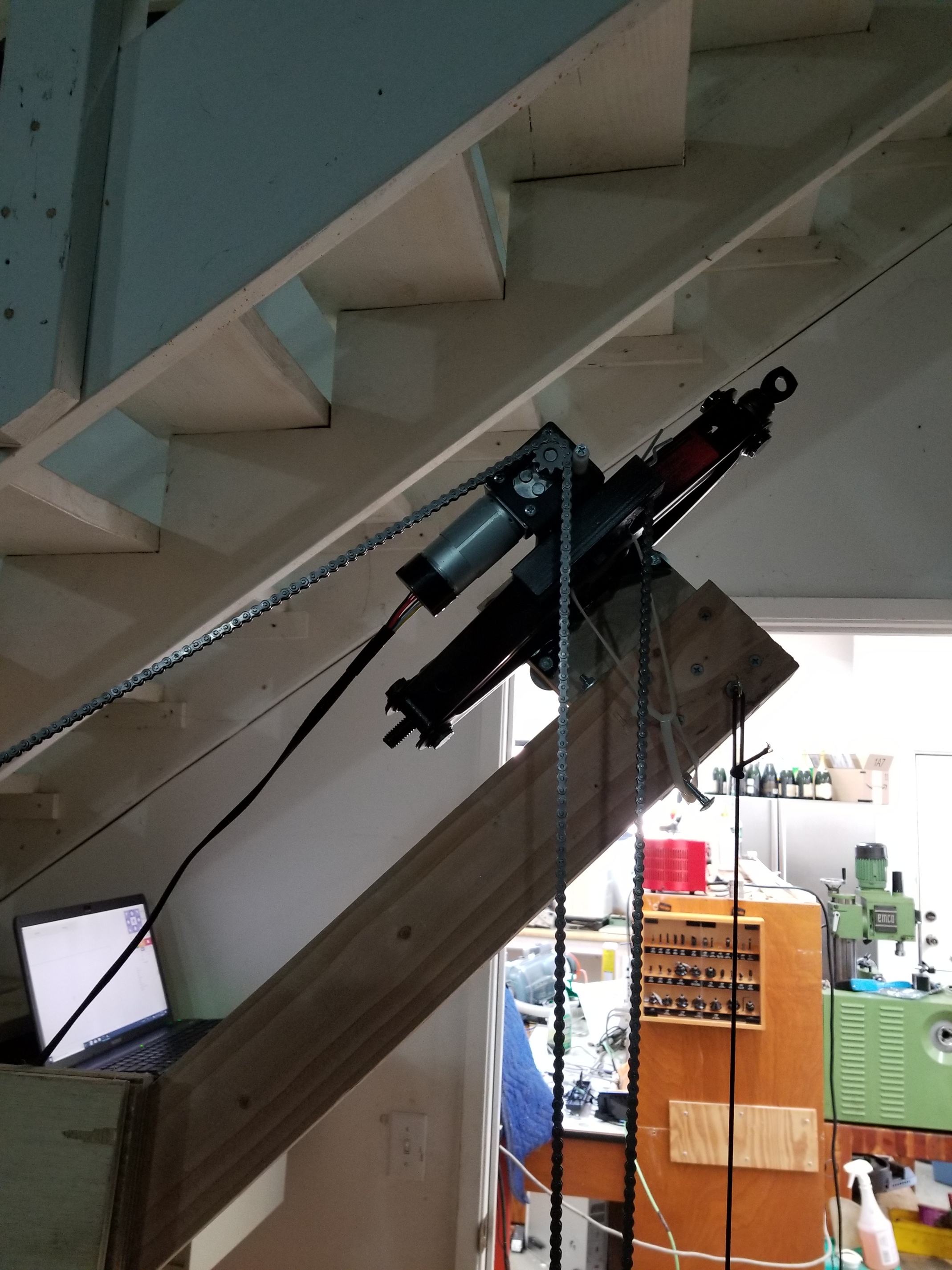
I know this is a little wacky but what about mounting the motors on a Jack.
Fasmov Scissor Jack-1.5 Ton,Black https://www.amazon.com/dp/B01MUODRKY/ref=cm_sw_r_taa_t9SoAb0DP0G8H
I like the idea. Now if we could just find a small one at a reasonable price
not as small, nor likely rigid enough, but closer to the right price range
I tried using the jack idea and it work pretty well. I had to use zip tie to keep tension as it did have some play.

4 Likes
nice work!
1234545675
Could the z axis kit that @StephenMcG used on his sled be used to quickly adjust motor mount spacing to account for material thickness? I think a manual adjustment would probably be more practical than cnc controlled. Could it be made stiff enough? It can be used for the z axis on a spindle so I assume it could.
There is a shorter version which would probably be all that’s required as far as adjustment. Unless you’re cutting thick foam board maybe?
I’ve been thinking about doing something very similar to that for a Z adjustment. You’d definitely want a cam or clamp or something to lock it into position mechanically during cuts but it could be a viable option. Keep in mind that 200mm is ~8 inches, so I think that would be plenty of travel for our needs.
How difficult would it be to program a couple of stepper motors to control that? It doesn’t need to be controlled by the G-code necessarily, it could be a manual adjustment in GC (maybe like the Z-axis?) The SCM group routers we have at work have a header value for material thickness, but that’s simply so that the machine knows how far above the spoilboard is the top of the panel it’s cutting.
I’m not sure if it would be as cheap as the scissor jack option, but it would be a neat feature for thicker materials.
you would have to add another arduino and driver board to control the steppers.
you are really overthinking this. This does not need rapid, or even automated adjustment. It needs to be changed when you are making drastic changes to the thickness of your workpiece. It’s not even clear that you would need to make the adjustment going between 1/4" and 1 1/4" material (i.e., set it for 1/2" or 3/4" material and you are probably good)
I never said I wasn’t overthinking it  To be honest, I haven’t even come into a situation where I’ve needed to adjust the motor positioning. The thickest I’ve ever needed to machine was 1 1/2", and I didn’t need to reset the machine for that. I’ve got bigger problems to solve with the machine than the motor height.
take a look at this and you can see the beam supported on short arms, and spacer blocks between the beam and the top of the frame.
top unistrut beam.pdf (419.8 KB)
If these blocks are the right length, you just take a piece of scrap of the thickness you are cutting and pinch it between the beam and the spacer, that will set the beam/motors to the correct distance, no electronics/jacks/etc needed. You can slot or otherwise make it easy to hold the top beam in place (frankly a large C clamp would probably be enough, there aren’t large forces here)
that last is a export from onshape (free account required) https://cad.onshape.com/documents/e635c24e358635f51da4b399/w/5a63b67113542f248fbe6d7b/e/7cf092bea21763650fb0c54c