I would suggest yes, but before you do, try lowering the Retraction Force and Calibration Force to 900 and confirm the belts Extend and Retract. It should be possible after tuning the spools.
If you have access to a 3d printer, check out the Maslow 4 3D printed parts thread, there are a couple of options to print replacement clamps and other useful things. I had the same problem and printed a replacement for the lower clamp.
With you anchor points you need some sort of support, 3D printed or a block of wood, Bolts, by themselves, tend to bend and won’t give you a reliable anchor point, especially when Maslow is getting close to corners.
2 Likes
hi, so I put the machine back together, and the retracting force 900 now pulls the belts easily!!!
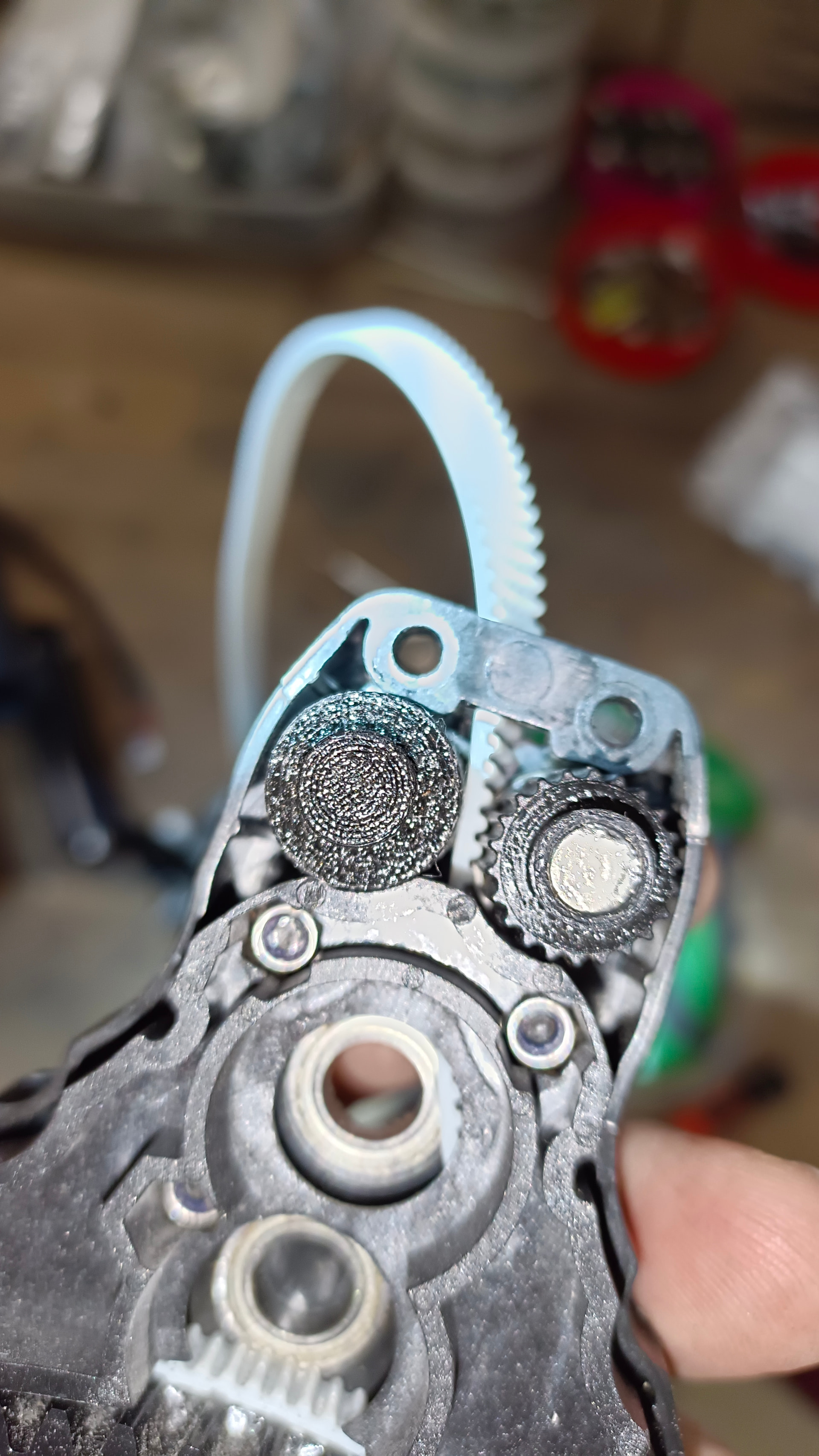
I ran the 2000x1000 calibration with 9x9 and forces 1000 and 900. the operation looks smooth, in the corners a little higher currents, more of a medium value. so around 1000 ±100mA

But it still wobbles when it goes along this line from the lower left to the upper left corner. It only bounces in this one direction. I have the anchor points parallel to the floor to the coils.
edit, attached serial code
Maslow-serial after second calibration - force 900.log (78.8 KB)
JURA23 wrote:
hi, so I put the machine back together, and the retracting force 900 now pulls the belts easily!!!
you may want to try lower if you can.
I ran the 2000x1000 calibration with 9x9 and forces 1000 and 900. the
operation looks smooth, in the corners a little higher currents, more of a
medium value. so around 1000 ±100mA
just for the record, the numbers are not mA, they are the PWM amount, 1/4096 of
max current (with >4000 triggering an alartm
Maslow-serial after second calibration - force 900.log (78.8 KB)
nothing interesting showing up here (other than it looking like you kept hitting
the calibrate button even after it had done calibration twice)
David Lang
yes, I can try again later with a lower calibration force.
Yes, I saved the serial after the second calibration, I’m trying the third one in a row. The second one was close to the real points. So I let go of the third one
on the debug window the unit under each motor is mA, so I guess it’s mystifying me.
another insight, I would like it if the values of the motors could be shown somewhere on the main Maslow window (tab).
so that the operation, serial code, and motors could be monitored at the same time. All that would be needed would be some sort of columnar display, from green>blue>red without values…
so that one does not have to switch between tabs
This could be solved by lowering the anchor points, lubricating the sled with wax so it glides smoothly over the surface, or reinforcing the anchor posts if they are too long. Personally, I use baby powder on the surface the sled will be in contact with.
JURA23 wrote:
another insight, I would like it if the values of the motors could be shown somewhere on the main Maslow window (tab).
so that the operation, serial code, and motors could be monitored at the same time. All that would be needed would be some sort of columnar display, from green>blue>red without values…
so that one does not have to switch between tabs
FluidNC has a telnet server, if you telnet to the maslow, you will get all the
logs and the current data that forms the graphs (I don’t remember if it’s
enabled by default or not, it’s one of the settings in the fluidnc tab)
David Lang
1 Like
Excellent!
This looks to me like it’s caused by friction between the sled and the wood that it is sliding on so I think this is not the same issue.
I think that this is an excellent suggestion.
The numbers he’s looking at are actually in mA. The software does the conversion
1 Like
A work around for this, open another browser window to the Maslow (so you have 2), on the 2nd window put it to righthand side of the screen with the currents displayed. Your normal window shrink until it fits the remaining space overlaying the secondary screen except for the current readings.

2 Likes
hi everyone.
I’m reporting a pretty good progress. I reduced the calibration and retracting forces to 600 and 700. I did a few anchor searches today and the result doesn’t look bad. Although I think the anchors are about 10mm different compared to the real one (I don’t have an exact measurement, just one approximate one).
Here’s a video after passing a 2.5x 1.25m area around the perimeter with occasional display of motor currents in the corners. It’s 4x faster.
I think it’s progress for me, I won’t be able to do it today, I have other work, but I’m already looking forward to cutting something out. It will still be necessary to fine-tune the axis scales, or manually enter the anchor location and compare which is better.
ps: yes and I was wrong earlier, I thought my frame size was 4.4x3.6m and it is ± 4.4 x 3.1m. I apologize for the mystification.
1 Like
hi,
so I’m reporting back after some time. Over the weekend, I adjusted the axis scales and made various trial cuts. And I’m cutting accurately again!
Accuracy to 1mm / 1m, the diagonals of squares and rectangles are 1mm. Retracting forces 800 and 600cal.
first it was a little bit jagged, so I added force. Now it guides more accurately.
I made some clean cuts. Apart from the problem with Gcode and error 66, I finally cut something.
I edited the video, it is 16x accelerated. cutting cladding panels for the van into 6mm plywood then into 6.5 hexa lamino plywood with a 3.125mm cutter. 2.5mm passage, so 3 passes.
I lost connection during the hexa plywood. The machine is then uncontrollable until you turn it off, retract the belts, and then extend the belts again and apply power, praying that it will continue on the same route after this restart.
Luckily, he made it!
3 Likes
I also wanted to thank those who advised me and helped guide and solve the problem. You are great !!!
Thanks a lot!
1 Like
I love the way the black wood looks while it is cutting! Great work!
Do you have the debug mode which shows the motor currents turned on?
I’ve seen that result in issues because the machine is sending so much extra data. I’d recommend turning it off except when using it for debugging.
