Is there a size minimum on the frame? I have a rather small on the sacrificial board 2 ft x 4 ft. The frame is 4 x 6 . Every time I put a .75 board under it I start having faults. I also have the same fault when I put the z axis all the way up for a dry run. Just seeing if anyone else has seen the same issue. Here is the serial log. I have ran calibration multiple times with the z axis bottomed out and it will run beautifully.
Maslow-serial.log (5.9 KB)
1 Like
Hmmm is this on a Maslow 4 or 4.1?
Generally you are on the smaller side of what can work, but it shouldn’t be impossible.
How does the tension in the belts feel?
Ross O’Connor wrote:
Is there a size minimum on the frame?
yes, something like 400mm square
I have a rather small on the sacrificial board 2 ft x 4 ft. The frame is 4 x 6
. Every time I put a .75 board under it I start having faults. I also have the
same fault when I put the z axis all the way up for a dry run. Just seeing if
anyone else has seen the same issue. Here is the serial log. I have ran
calibration multiple times with the z axis bottomed out and it will run
beautifully.
take a look at the frame calculator http://lang.hm/maslow/maslow4_frame.html and
see how far out of the green area you are going.
you should do the calibration with a board the thickness of your workpiece in
place (and check that the Z offset values in the maslow.yaml file are sane)
with such a small difference between your workpiece and your frame, you may be
running into problems with the angle of the belts (in the Z direction) and may
benefit from moving the anchors to where they are closer to level with the arms.
David Lang
1 Like
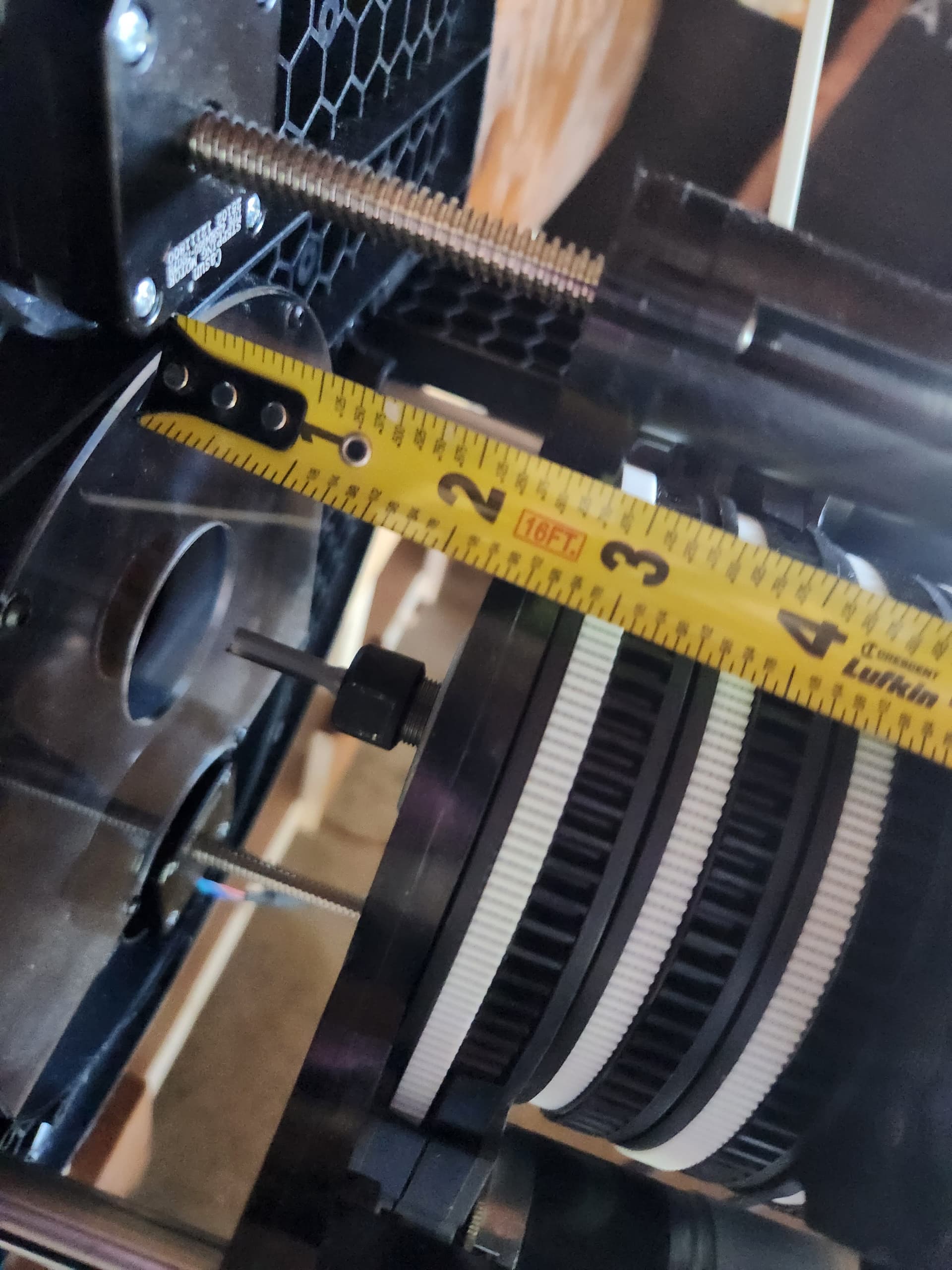
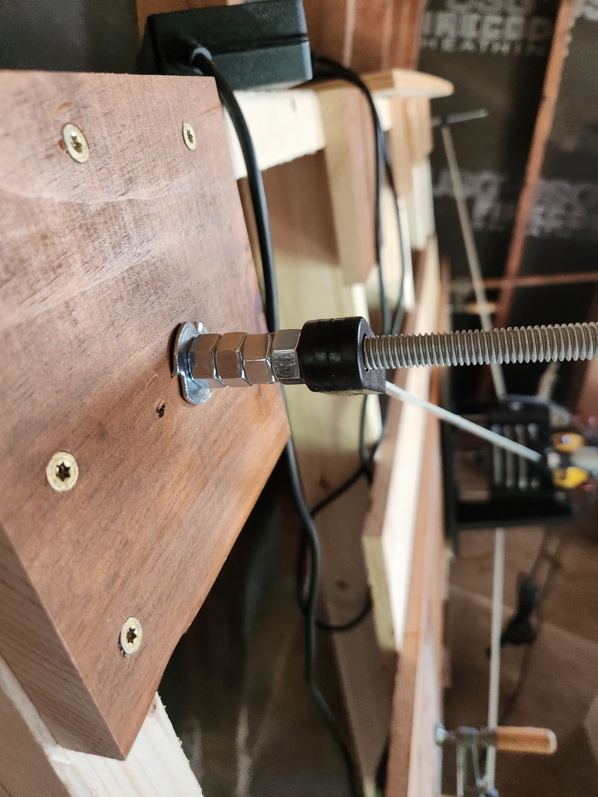
@bar it is 4.1. The belts are tight and have a steep angle. I had increase the extension by 10mm to even get them on. Which on a side note, we really need a way to manually over ride and release the tension if there is a problem. It is rather difficult to get them off when full tension is applied. I am guessing this is a safety feature to keep it from dropping. Maybe a release button that lets out a mm or so each time it is pressed.
Overall this would be awesome information to share on the frame building page. I was under the impression it was a lot more open to sizes.
@dlang your calculator helped. It took me some time to understand it. If it is going to the public could you do a quick walkthrough on a video? Also, I get a bad gateway when I click the link. I think this is because I am on my work laptop currently.
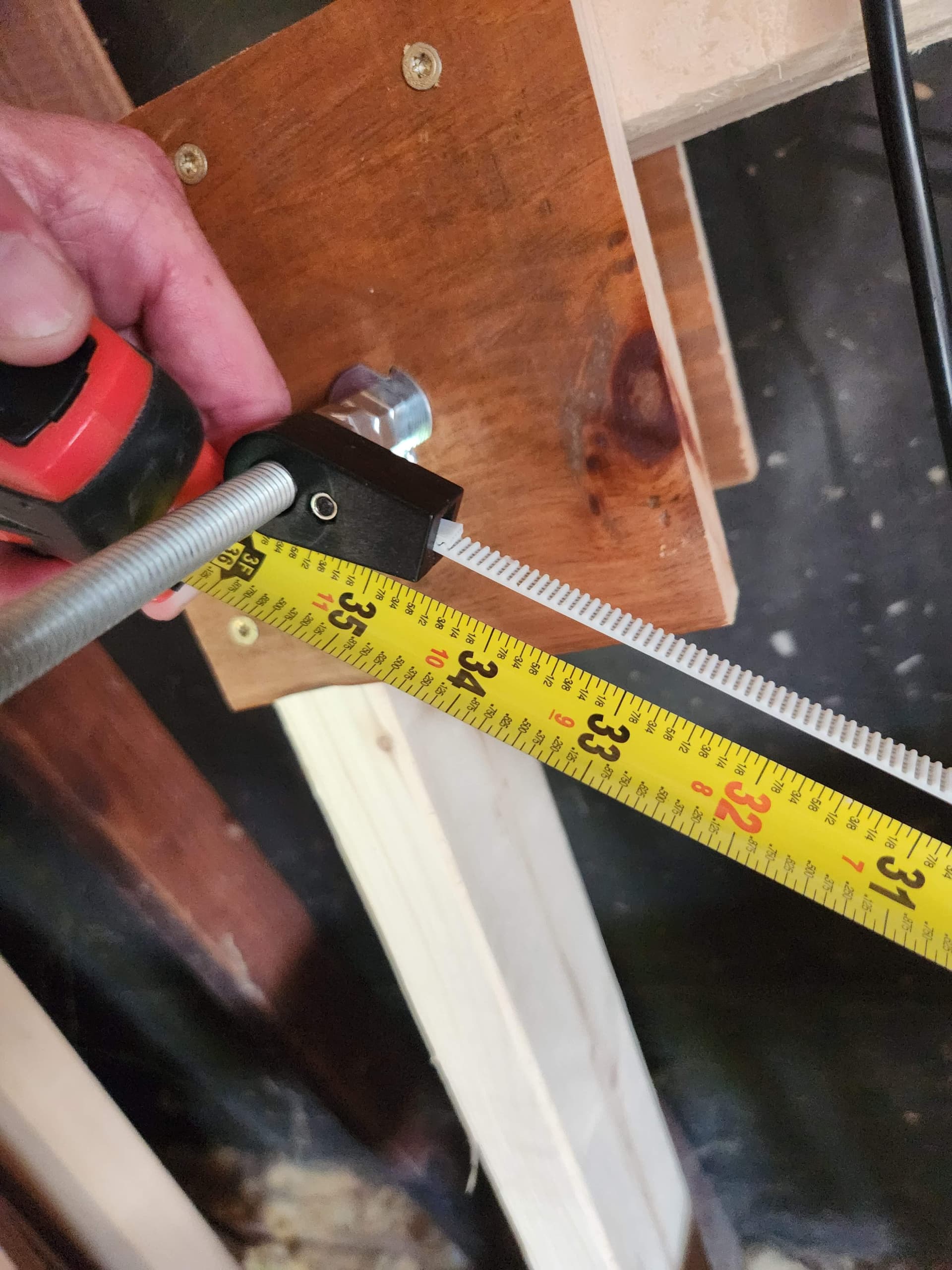
I am thinking of putting longer bolts in with a double nut to hold the belts more in line to keep them closer to 90 degrees based on what you said
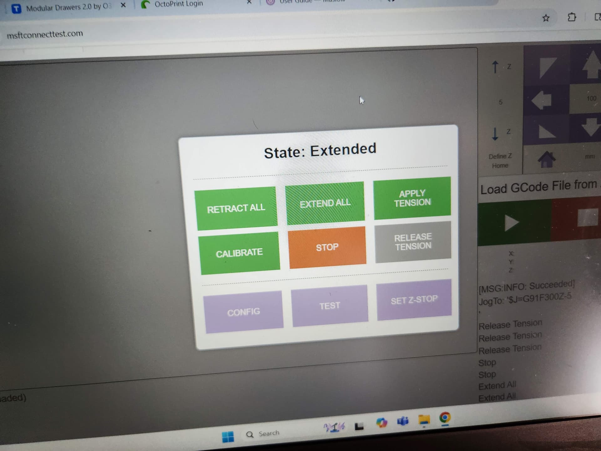
The “Release Tension” button should do exactly that ![]()
The steep angle seems somewhat concerning. How steep are we talking?
Understood but it would not do anything for me in this state. Fan didnt kick on or try to move when I pressed the button. I figured it was a fail safe of some sort.
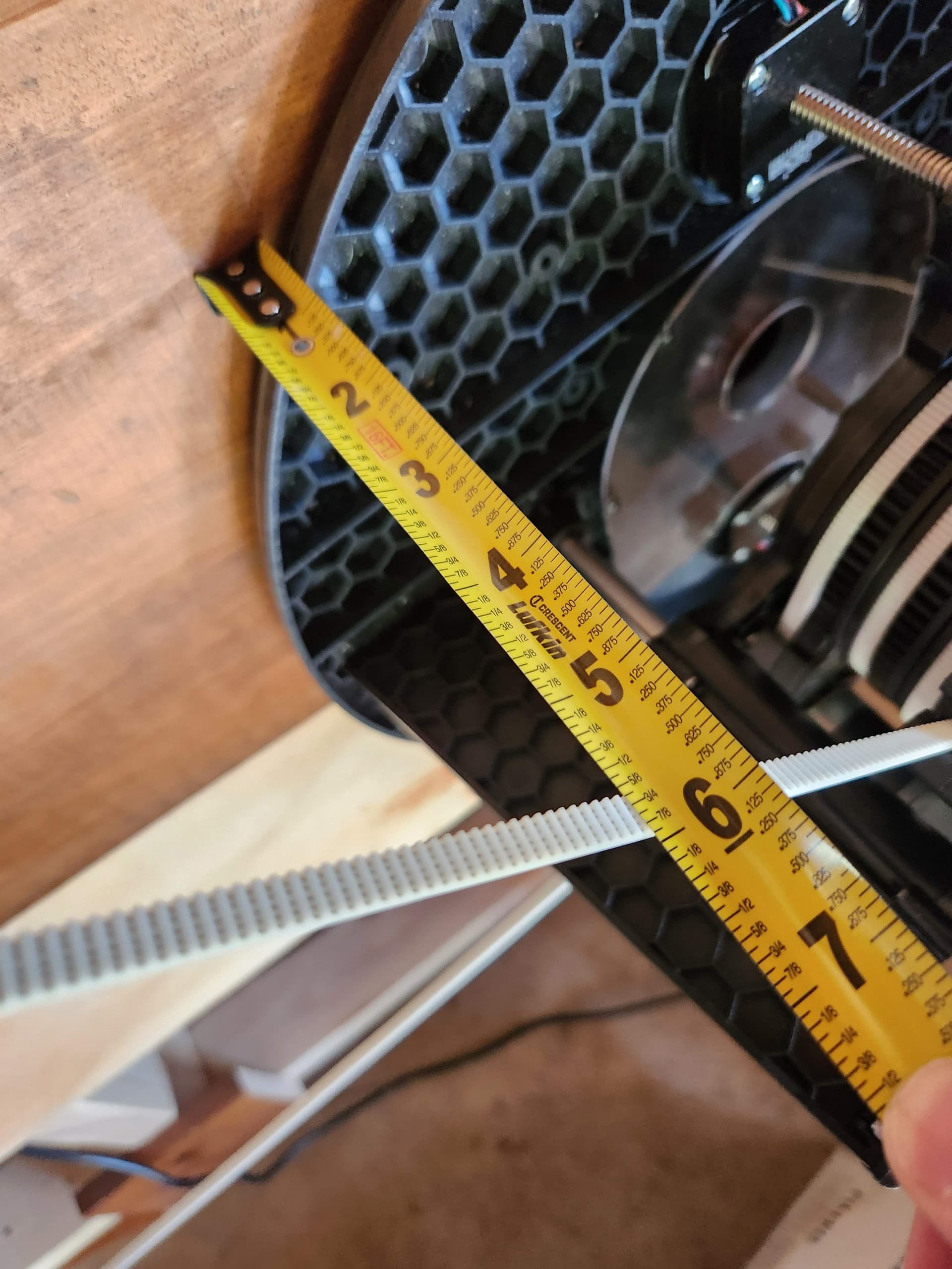
I am really not sure. My guess is 30 to 45 degrees. It was almost at the top of the z because I had a router bit in and was doing a dry run. I could set it up and measure it this weekend if it would help.
I’m not completely groking the tool…
How bad is the distortion in the peach and yellow colored areas?
Ross O’Connor wrote:
I am really not sure. My guess is 30 to 45 degrees. It was almost at the top
of the z because I had a router bit in and was doing a dry run. I could set it
up and measure it this weekend if it would help.
that sounds like enough to be a problem (it will flex the arm down and add
friction making it harder for the arm to pivot)
see what you can do to raise the anchor a bit (and change the Z offset to match
what you change)
david Lang
Dave Covert wrote:
I’m not completely groking the tool…
How bad is the distortion in the peach and yellow colored areas?
each band in those areas is 1 degree of error on the belt. how much that changes
the length will depend on how long the belt is. just above the graph there is a
table that shows what the effective belt length would be if it’s supposed to be
1000mm
David Lang
I am assembling my M4.1 now and will soon be building the frame. I have a solid 4x8 work table with a piece of sacrificial ply on top and plan to bolt on 24" out riggers to each corner to make a 3300x2084 frame.
Can I get an opinion on this plot? I will typically use the 4x8 area only when cutting cabinet body sides out of whole sheets of 3/4" ply. Artsy stuff will almost always be within the green area.

Dave Covert wrote:
I am assembling my M4.1 now and will soon be building the frame. I have a
solid 4x8 work table with a piece of sacrificial ply on top and plan to bolt
on 24" out riggers to each corner to make a 3300x2084 frame.Can I get an opinion on this plot? I will typically use the 4x8 area only when
cutting cabinet body sides out of whole sheets of 3/4" ply. Artsy stuff will
almost always be within the green area.
the artsy stuff tends to be more forgiving of errors. the cabinet joints and
edges being off or not straight lines tends to be more of a problem
my frame calculator is only looking at angles, Bar’s has toggles for more
per that, you will also run into grief in the corners from the belt angles down
to anchors at tabletop height. You can bypass that problem by raising the
anchors so that they are close to level with the arms at Z zero
David Lang
2 Likes
@dlang @bar
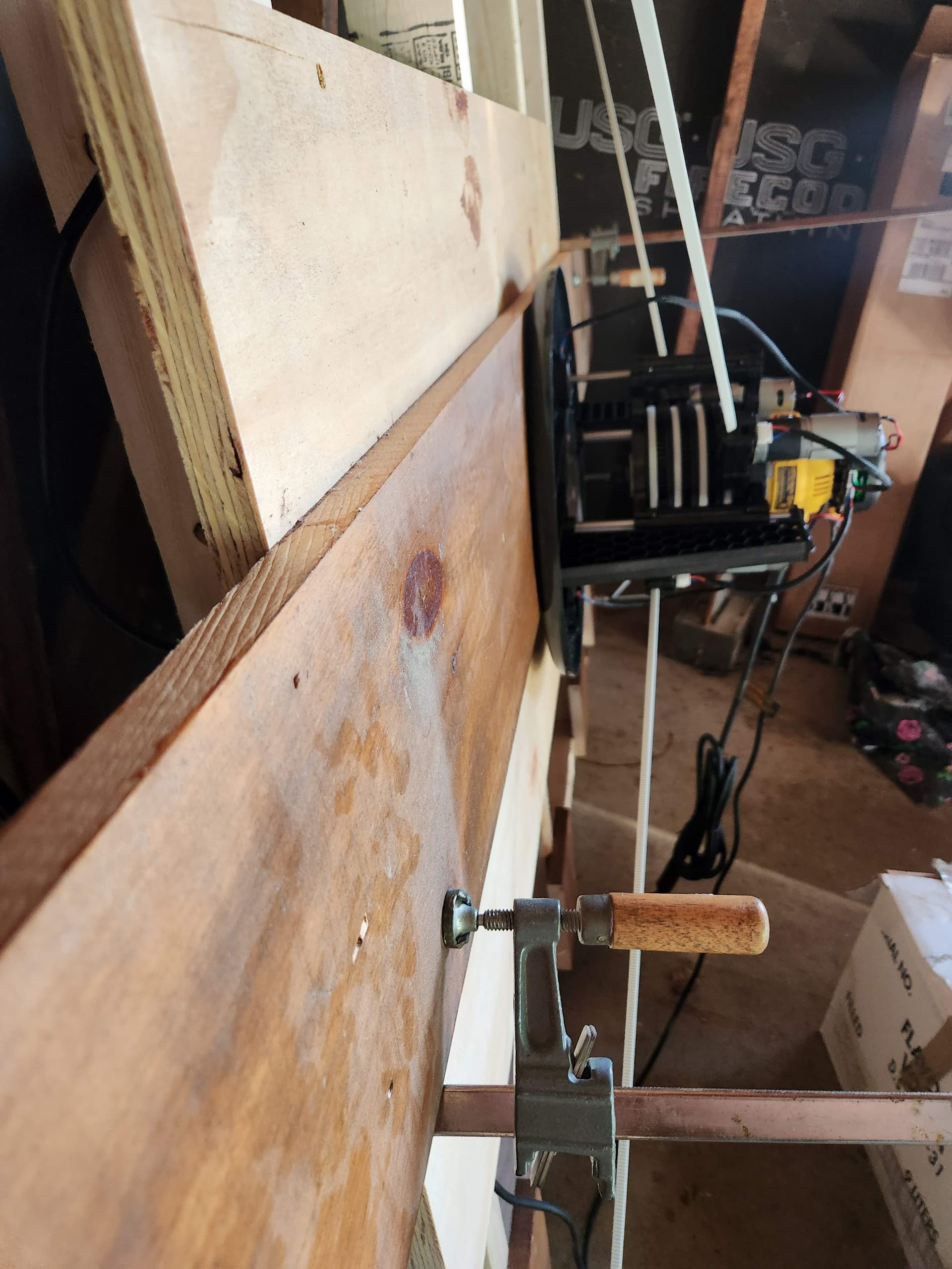
Finally getting back to this again. I am thinking my frame is just too small. See attached for a few pictures. As you can see the release button is grayed out. I am thinking of recalibrating it with the board I am trying to machine under it before making a whole new frame. Added over an inch with the nuts.
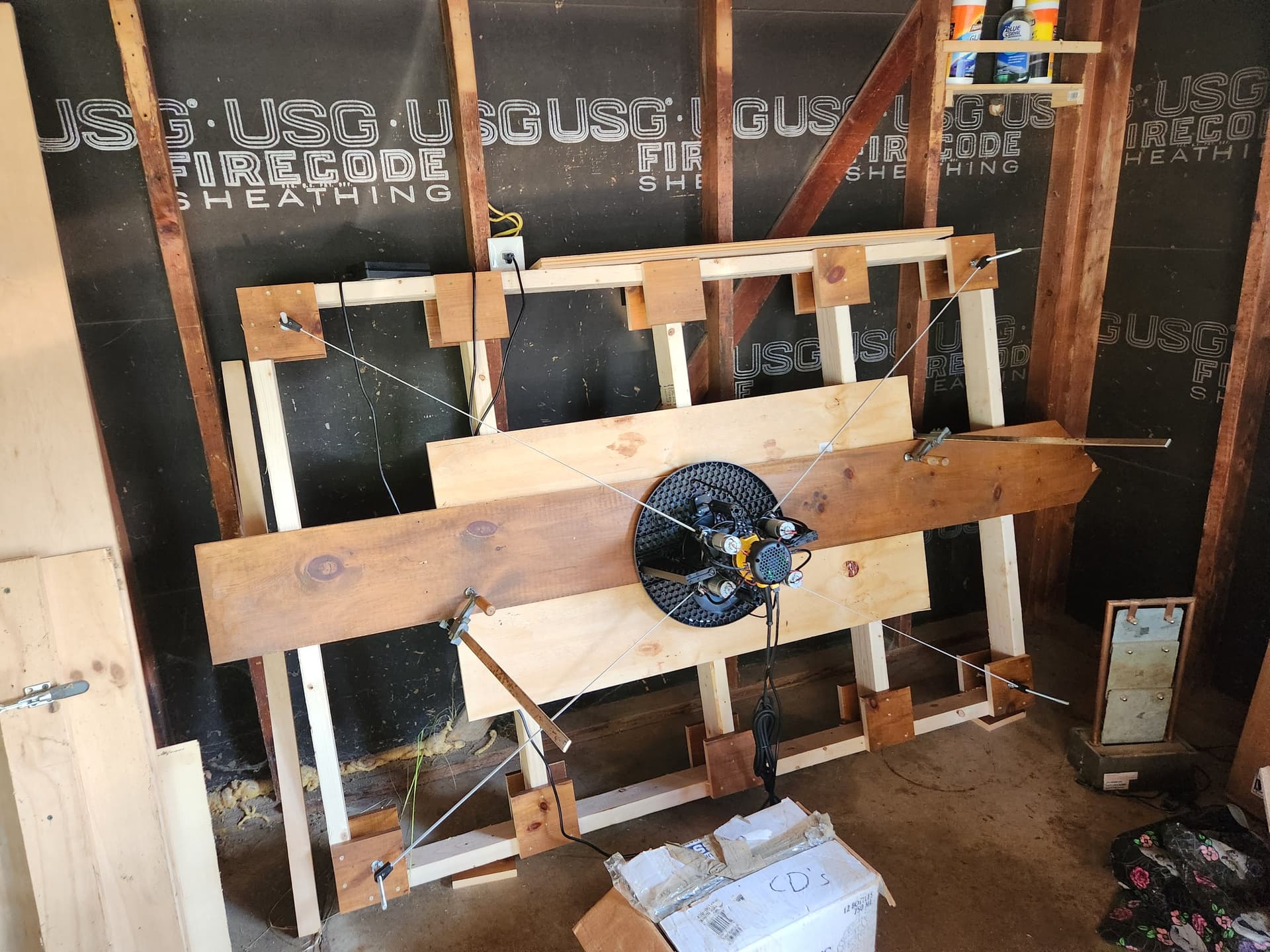

Ross O’Connor wrote:
Finally getting back to this again. I am thinking my frame is just too small.
See attached for a few pictures. As you can see the release button is grayed
out. I am thinking of recalibrating it with the board I am trying to machine
under it before making a whole new frame. Added over an inch with the nuts.
one thing is that you need a nylock nut on top of your anchor to keep it from
moving up the anchor rod.
what is the size of your frame and the size of the area you are trying to
calibrate or cut over.
here are two tools to check your size.
http://www.lang.hm/maslow/maslow4_frame.html
David Lang
Sacrificial board 2 ft x 4 ft. The frame is 4 x 6. Everything looks green on the first tool. Last idea is to calibrate over the piece I am trying to cut. Its a pain when it stops like this. It is difficult to get the Maslow off the frame
Ross O’Connor wrote:
Sacrificial board 2 ft x 4 ft. The frame is 4 x 6. Everything looks green on
the first tool. Last idea is to calibrate over the piece I am trying to cut.
Its a pain when it stops like this. It is difficult to get the Maslow off the
frame
take another look and enter the size in mm (1830x1220 frame and 1220x610 for
workpiece) and you will see that you go out of the green in the corners and the
top/bottom center
if you enter the values in inches, the lines are too wide and make things look
better than they are.
David Lang