I recently started cutting with my Maslow 4.1 and have managed to dial in the cutting parameters pretty well. The repeatability of my cuts is better than 1mm, which I’m happy with so far. However, I’m seeing a systematic error of about 5mm in the Y-direction — even when cutting near the center of the workspace.
Back during initial setup, I ran into issues with the calibration procedure and read that manual calibration can be a viable alternative in cases like this. So I decided to go the precision route:
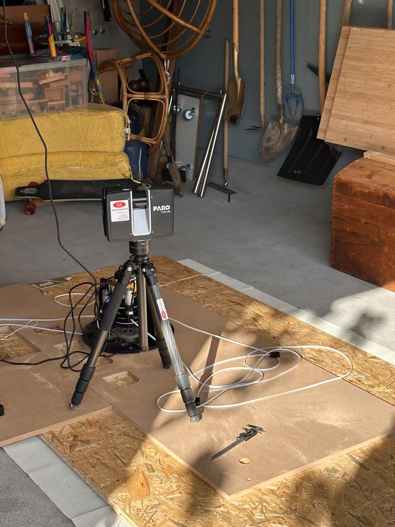
I made custom anchors with 10mm H7 bores, and cemented them into the garage floor for long-term stability. My goal here was to ensure the frame size remains accurate over time. I then measured my anchor points using a Faro laser scanner, with an expected accuracy of ±1mm.
I’ve just started comparing the software calibration with my actual scanned measurements. That said, I made a small mistake: I forgot to lower the Z-axis to the bottom before running the calibration, which may have influenced the results.
I’m currently on a business trip and won’t be able to re-run the calibration or cut parts until next week. But in the meantime, I’d appreciate any input:
Should I adjust the tlz, trz, blz, brz values manually?
My anchor points are flush with the floor, and I’m using a 22mm thick spoil board.
I know your question was about z, but maybe this is a small encouragement: I’ve seen a definite improvement from using manually measured x/y anchor positions instead of the result of the automatic calibration. I then also had to adjust belt tension by scaling the frame measurements very slightly. If you are in for a long read, go ahead, but be aware that it’s still work in progress and I feel like not knowing anything: Feedback on calibration and resulting dimensional accuracy
Oh, and about that Faro scanner: Get rid of it. Throw it my way. (Okay, I admit I’m just a little bit jealous … I can’t even count how often during my home renovation I wished I had such a tool!!!)
This! I must have missed this tip since (when) I did my first calibration in the set up guide. Questions::
Does the Z need to be all the way down with a bit, or without (the later would be lower)?
Should the calibration be run on the spoil board, or on the material the parts will be cut from?
I also found out that my Maslow binded going all the way down after the 4.1 upgrade, probably due to my assembly, but I was albe to spin one of the stepper motors to even it out. Maybe lowering the Z is a good post assembly test.
Does the Z need to be all the way down with a bit, or without (the later would be lower)?
without
Should the calibration be run on the spoil board, or on the material the parts will be cut from?
on the material you are cutting (and make sure the Z offset values include both)
I also found out that my Maslow binded going all the way down after the 4.1
upgrade, probably due to my assembly, but I was albe to spin one of the
stepper motors to even it out. Maybe lowering the Z is a good post assembly
test.
you may need to loosen the screws holding the steppers, then lower it all the
way, then tighten them (alignment)
Thanks.. I did re-read the user guide and see it mention without bit.. I will now remember this.
I did not find any mention of how to set the z offset (can you point me to a souce?). My belt anchors are on 1.5" block risers. Is it possible to use a negative z offset or should the top of my materials be at least level with the achor bases?
I did not find any mention of how to set the z offset (can you point me to a
souce?). My belt anchors are on 1.5" block risers. Is it possible to use a
negative z offset or should the top of my materials be at least level with the
achor bases?
The Z offset values are in the maslow.yaml file, you can either edit it or you
can set the values in the settings tabl next to where you would upload files.
it’s best if the offsets are not negative (a negative offset means the belt will
pull the machine away from the workpiece)
It was your post that motivated me to take accurate measurements of my anchor positions. This weekend I’ll have a bit of time to test things out and compare the measured positions against the automatic calibration – I’m really curious to see how much of a difference it makes.
Unfortunately, the Faro scanner isn’t mine – it belongs to a friend who does scanning and design work for renovations professionally. Luckily for me, the scan only cost a few beers and a BBQ
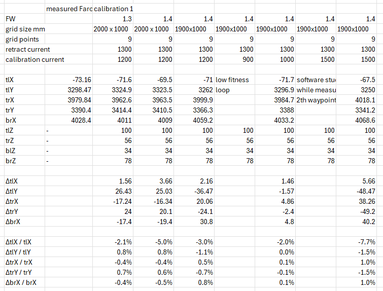
I finally had the chance to run a quick comparison between the automatic calibration and the Faro measurement data. While it’s just a single repetition per test, the initial results are interesting.
What stood out: lower calibration threshold currents appear to yield better accuracy. Specifically, with a threshold current of 1000, the results were very close to the Faro measurements.
Very helpful! I had assumed it was the actual height of the anchor point but your post implies height_of_belt_on_Maslow - height_of_anchor_point_above_cutting_surface.
Which raises the question: Maslow knows its height and compensates that in the calculations but cannot know the thickness of the board you are working on. Should the anchors be raised by the thickness of the workpiece?
Which raises the question: Maslow knows its height and compensates that in the
calculations but cannot know the thickness of the board you are working on.
Should the anchors be raised by the thickness of the workpiece?
the z offsets should account for the thickness of the qoekpiece and the
wasteboard.
Back on this thread ( V1.05 Firmware Quikie Questions ) where I was playing with turning of the x and y offsets I mentioned that I noticed that the accuracy of the y axis became worse closer to the anchor points (the measurements grew).
I pulled out an old spoil board where I drilled holes every 6 inches over the board in several passes, but then the new 4.1 hardware was coming out so I shelved the Maslow until I did the upgrade.
With the old hardware and firmware, the Maslow was very accurate. Within 1/32 over the usable cutting surface. So, somehow I lost accuracy with the changes to 4.1 and firmware 1.05.
What would you suggest I should try to get things back to uniform?
The 4.1 and 4.0 hardware shouldn’t affect the calibration so if you have a backup of your old maslow.yaml file you should be able to just load that one in (or maybe better to just copy the anchor point locations out of it and enter them in the settings). That should get you back to the same way the machine was behaving before the update