Easy fix. In settings change your Z-axis pitch value to a negative number. Negative number will go one direction positive number will go the other direction.
1 Like
Your Z-axis pitch needs to be made a negative value. The motor is spun around 180 from it’s stock orientation, so it turns backwards compared to what the firmware is expecting. See this post from this thread about calculating the correct pitch and where to enter this value.
Also see this post about calibrating the pitch.
Hi, I am trying to put together the parts but I am confused about the pulleys.
What is needed is two XL 16 belt pulleys? I am confused by the optionals.
Thanks
The optionals are all different options for running the axis at different speeds. I will be conducting some testing regarding this at some point in the near future. What you need to build it is two XL pulleys, one with an internal bore of 6mm and one with an internal bore of 8mm.
Do you have a updated version of your design in Fusion 360 with the holes for mounting the ring system to the sled? I know you posted the g-code but I have found the the material stock I am using is a different thickness then what your design works with and the “pegs” are not fitting in the holes.
The url to the model is in the instructions in the community Garden, although it doesn’t seem to creating a link. I’ll have to look into it at some point to make it a clickable link.
In case you’re having trouble navigating here, this is the link: http://a360.co/2jWip1u
You’ll want to update one of the user variables, Ply1, with your measured plywood thickness:

2 Likes
Thank you sir. I can’t wait to get this new sled up and running.
Thats a piece of beauty.
I have cut out all the plywood pieces and cleaned them up. I had a few ideas that I thought would be helpful.
- Create a template which defines the placement of the rail-blocks. This would be like a rectangle, with 4 rectangular holes cut in it, one for each mounting block. Line it up on the vertical base, and place one mounting block into each rectangular hole. It would be an alignment tool. Something to help place all the rail-mounts.
- The other idea is related to the router clamps. The idea is to make the part where the bolt/screw goes through to be longer. A simple drawing is below. The goal of making it longer is to move the bolt/screws closer to the router. This makes the tension align with the wood ring, so the tension force goes through the center of the wooden ring, rather than being cantilevered out past the wood-ring. In the drawing, there are two examples, old vs. new, which show the change for one-bolt and two-bolt rings.

3 Likes
See this post from this thread for the carriage template.
That will be a moot point, however, when I finish my current round of revisions. The mounting holes have all been transferred to the carriage and will be drilled by the Maslow.
Do you mind modelling that up? We’ve had a few different versions of clamps in this thread, I haven’t found a version of the wooden clamps that I’m confident in. So far, the printed/my machined ones have been far superior.
1 Like
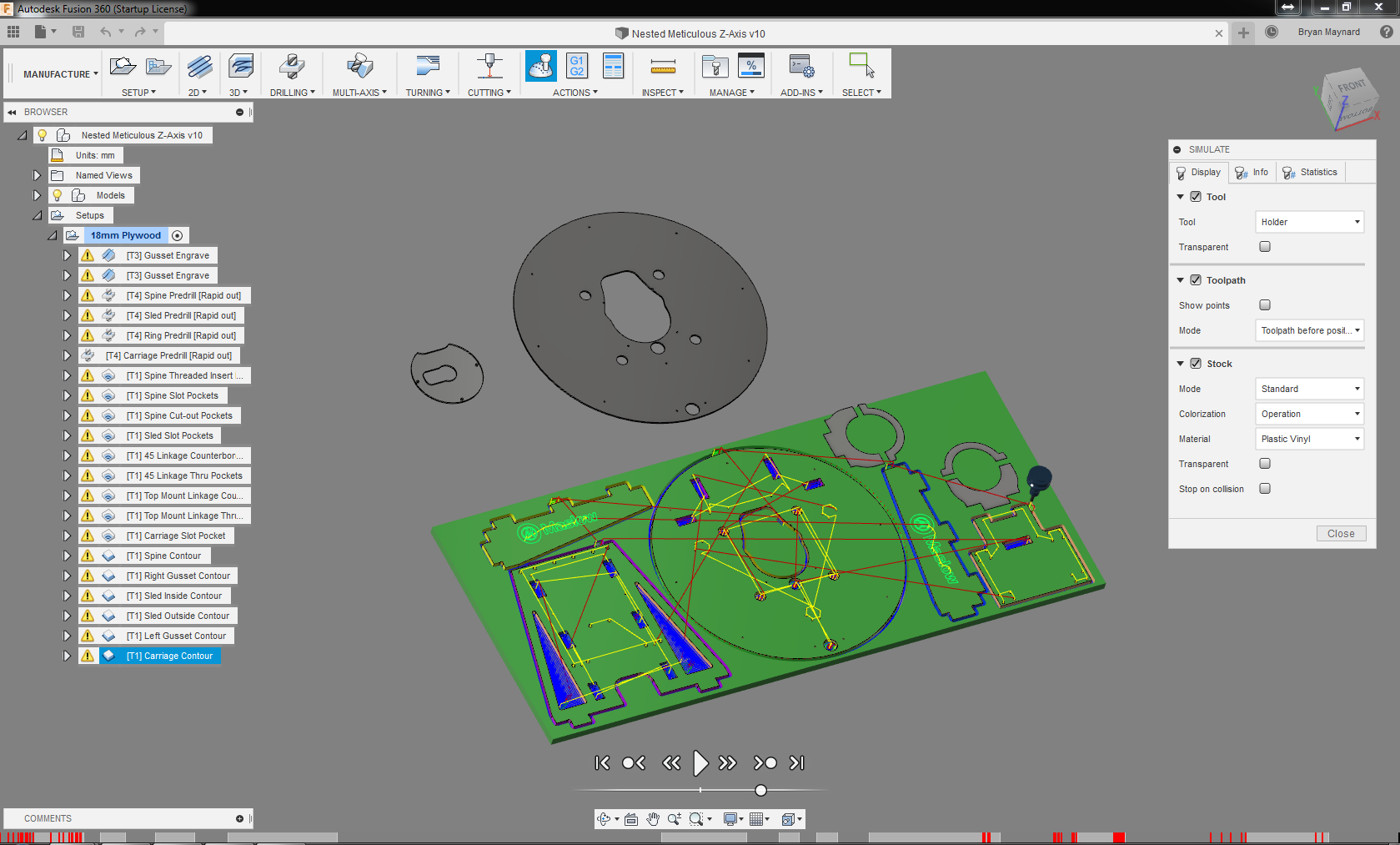
I’ve been talking a lot about updates lately, and while I’m not ready to publish NC files to the Garden, I have enough progress that I can make my nested Fusion files available.
So far I just have the 18mm plywood for the main version programmed. I would like to test a couple new CAM features I’m using before posting and releasing nc files. As of now, these are untested programs, so be cautious running them.
I have not programmed the 0.250" HPDE sled skid pad, or the 0.125" acyrlic dust chute for the main version. I also have not even started on the plywood version. I do want to make them available so that people can work off of the Fusion files until I finish doing the NC files.
Nested Main File: https://a360.co/2KUE4Hc
Nested Plywood Version: https://a360.co/2VhulyW
7 Likes
Quick question: which operation is t6?
Where do you guys sourced the 150mm long bit? At grainger they couldn’t figure it out.
Are you cutting the plywood dust hood? That’s the only part that requires that tool.
From the instructions page on the community garden:
That tool is 1.5mm in diameter. This is the particular tool that I programmed it for. You can also run a 1/16" bit.
No, I printed those. So I don’t need this bit.
Talking of the print, I tried at 50% infill but it seems still brittle, especially the two “horns” of the chute. What do you guys print them at?
Thank you for your help, I’m looking forward to try it.
I printed mine at either 10% or 15% and it’s been good. I did print it with the thickest walls I could, though, so the part you’re talking about is probably “solid”.
Good luck with the build! Hopefully you’ll have it running in no time 
I am looking at ordering the dust chute from 3Dhubs.com. Can someone experienced with 3 D printing please advise on these options?
- 100, 200, or 300 (micron meters? nano meters?) layer height?
- Infill percentage
- Material - is PLA ok? Stainless sounds cool, but $1500 seems a bit steep for a dust chute.

1 Like

Could easily be a bad model. I just checked my model in SolidWorks and it likes the mesh.

Try uploading this one and seeing if that works any better. Maybe their software just doesn’t like my stl? xD
Dust Hood Chute V2.stl (593.2 KB)
Not sure what unit that layer height is in, I would guess microns but I’m not certain. It’s a cost vs quality trade-off. The lower the layer height, the finer the Z resolution is. But it adds more layers, which adds to print time.
As far as infill, you shouldn’t need it to be too dense. As it is, it has relatively thin walls, so infill won’t affect it much. I printed mine with extra perimeter passes, as well, so mine may be close to solid anyways.
PLA is a great material for it 
Though I did check my Shapeways page and saw they can print it in steel for just under $800.00.
If I ever work at a place with a metal 3D printer and they let me print my own stuff on my own time, should totally give it a go 
2 Likes
Here it is _
Thank you
1 Like
hi there! is the final draft of this ready to be downloaded and cut by the maslow yet? ive been keeping tabs on this thread for about a year now and i actually cut one of the earlier versions without the predrill holes for alignment. i was not able to use it but since then my maslow has become even more temperamental. i dont think it will be able to cut this at all. im curious if there is a way i can print this out, to scale, and glue it to some ply wood and cut it out by hand. or overlay the print out on what i had previously cut so that i can attach all of the metal parts.
if it is ready then maybe i can find someone who can cut it out for me and ship it.
im having an incredible amount of issues with my maslow over the last year and im really hoping this can get me back on track.