Yes, it’s LinuxCNC ported to the beaglebone black and definitely uses the PRUs for step generation. Iirc there was talk of and possibly ports of machinekit to other hardware but I wasn’t interested or followed any of those, but if it’s BBB you want you get PRU support. Giggle machinekit bbb pru for more info. On my phone or I’d invoke the fu and link
thanks, I found http://www.machinekit.io/docs/man/man9/hal_pru_generic/
this has PWM output and encoder input (as well as stepper output), there isn’t a
servo output, but I’m not sure we could use one without having to put the entire
kinematics/PID functionality into the PRU (and I don’t know if it could do all
of that) since the motor motion and sled motion do not have a linear
relationship.
but this looks like it could work to test the assumption that the timing is not
that critical for the PID loop and support existing motor/encoders (but needing
a different motor board or at least remoting the board with a maze of wires for
testing)
you mentioned that there was something resembling the maslow kinematics in
machinekit somewhere?
a couple things that popped up in my inbox from adafruit
they have a couple motor controller boards that you just talk i2c to and they
generate the PWM on the board to control the h-bridges (limited to 1.2A, so not
suitable for the maslow directly, but an idea of what can be done and how you
can build a 2 motor system that can easily be expanded to 4 motors or more)
same thing in two different form factors
and a breakout board with a motor controller that we may be able to use, up to
3.6A @48v using a DRV8871 chip (current limiting, thermal shutdown)
The fu is strong with you, young chainwalker
3 Likes
That goes back to my suggestion of isolating motor control from the microcontroller that’s running ‘grbl’. If you just leave it to the motor controller to accept pid inputs and report error, then you eliminate all the real-time requirements needed for the ‘grbl’ part and therefore can run on something like an RPI.
You would still have to sync some settings (pid values) between the RPI and the motor controller, but it would allow you to reuse work that’s already done (web control). Rather than rewriting grbl into webcontrol, you could run webcontrol (python) and a de-motorized version of grbl (c++) on the same RPI since it can handle multitasking and all the real-time components of grbl were shifted to the motor controller. Eventually you might be able to evolve the entire operation onto the motor controller if you use a powerful enough microprocessor for it (i.e., like a large memory esp32)
1 Like
I wonder if this is what the Yetitools SmartBench is doing. They are quite open about using the Pi for the UI and controller but they also reference grbl in some of their videos.
Jeff
Could you expand on that a little? When you say PID values, are you just talking about the setpoint, or also Proportional, Integral, and Derivative coefficients? It just struck me that for most machines PID coefficients are constant because the basic machine response does not change with position. But Maslow has different optimal PID coefficients at each position on the board.
Does existing code actually go to the trouble of calculating and updating these values at every position?
If so, that is really cool!
If not, is that feasible? It would be difficult to map out the optimal values to start with.
They would vary slightly with individual machines, but a general map should be good enough given a specific motor/controller/machine aspect ratio. The benefit would be much more linear appearing response from the point of view of higher motion planning algorithms, thus less error accumulation, more compatibility with generic machine controllers.
After thinking about my idea for a while, I don’t really know the true value of it since you can get the entire grbl running on the microprocessor easier than you can get it running on a RPI.
Regardless, I was suggesting sending pidsetpoints to instruct the motor controller where to go as well as sending the PID coefficients as setting so the motor controller could be updated. I don’t think for traditional maslow designs that the PID coefficients change depending upon where you are. Working on a four motor design with the rope self contained on the sled, I saw that it might be necessary to do just that because the circumference of the spool that held the rope changed over time as the rope intentionally wrapped on itself. but thats another story…
Ironic. The affects of wrap layers are highly predictable and depend only on one cable length. Optimal PID coefficients (on Maslow, not in general) are constantly in flux and have many variables. It took the later to prompt the former.
Here is the layout I am leaning towards now:

Or if you want an interactive version: Maslow Create 
The Bill Of Materials works out to:

Which seems pretty reasonable to me.
Can anyone find a part number for some 15 place .100" surface mount female headers? I can’t find anything but maybe by digikey fu is just off today 
3 Likes
Hi there!
You may want to check this out, they are in California and they are a reliable source.
Phoenix Enterprises
https://www.peconnectors.com/female-headers-pcb-1x-row-.100/hws1879/
1 Like
Looks good! Is that ‘DRV7783’ in the BOM meant to be ‘DRV8873’?
1 Like
@2cents Do you know if they make a surface mount version?
@blurfl I sure do! Thanks
Edit:
I was able to find some from DigiKey, but nothing in stock. Here’s what they have:
https://www.digikey.com/product-detail/en/sullins-connector-solutions/NPTC151KFXC-RC/S5607-ND/776065
https://www.digikey.com/product-detail/en/samtec-inc/SSM-115-L-SV-TR/SSM-115-L-SV-TR-ND/7858764
1 Like
Here are some possibilities…
Edit - this limits the list to include ‘in stock’ and ‘active’, a much shorter list…
1 Like
Sorry I missed the “surface mount part” : p
Check this at Mouser
1 Like
Nice finds guys! Thanks! Those are exactly what we need. Awesome work.
1 Like
So the ports are X, XX, Y,YY & Z?
Thank you
I was kinda planning to just call them 1,2,3,4. They aren’t really on an XY plane so I think maybe calling them XYZ would be not completely truthful. What does everyone think?
Right now I’m just working through everything to see if a 4 cable (5 motor) machine is feasible from a cost standpoint and trying to figure out what all the parts would be. To check to make sure the ESP32 has enough pins I put together a quick list of what we need. Thanks to @blurfl’s brilliant suggestion to use the LED controller chip I think we have easily enough unless I forgot something:

1 Like
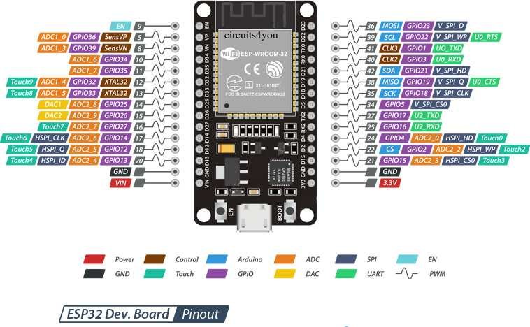
I agree there seem to be plenty of pins. There could be a problem with ‘Analog Current… Motor 1’ on the pin shown in the diagram (30-pin version of DEVKIT). I don’t think that pin (gpio16) is ADC capable. Also, ADC2 pins (0, 2, 4, 12, 13, 14, 15, 25, 26, 27) cannot be used when WiFi is used. Take a look at the section headed ’ Analog to Digital Converter (ADC)’ on this page.
Here’s a pinout that I’ve found useful.

3 Likes