re: Top Beam attachment to the frame.
Splitting off of the 800+ post thread
How should the top beam be attached to the frame
For the standard frame, the top beam will not be adjustable.
The version 1 approach of attaching the motors to a piece of plywood and attaching that to the frame is something we want to get away from, the plywood flexes and the attachment to the frame has proven to be less than rigid (even with a lot of screws driven into the joint). And finally having the motors stick out gives them leverage to flex the frame.
We’ve talked about having several layers of 2x4 spacing the motors out from the top beam, but that has alignment problems and still gives the motors the ability to flex the frame
As a result, we are wanting to attach the motors directly to the top beam roughly as shown in the pictures of Bar’s work, for example
For the standard frame, the forward face of this top beam should be about 6" forward of the face of the leg.
We have looked at multiple ways to do this, none of them is obviously right, and all of them have problems
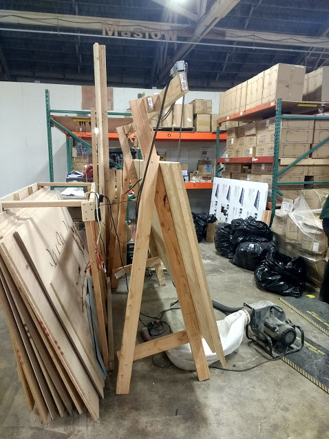
One approach is what is pictured in the picture above, with short lengths of 2x4 attached to the legs and the top beam attached to these supports.
- The difficulty with this approach is how to attach the top beam to these supports.
We’ve discussed many opttions
- (current thoughts), lay the board flat so it’s easy to fasten (there is a little movement as a result)
- have the board upright, with a block behind it (how do we keep it from being tilted as it’s fastened, the front of the beam needs to be parallel to the legs/chains/etc)
- have the board upright and drill through the long dimension of the 2x4 to fasten it to the supports (how do you drill a good straight hole)
- variation of the last, drill through the support and have the bolt/screw from below (similar problem but only one end of the hole needs to be in the right place)
- use a heavy duty angle bracket and piece of unistrut (trivially modifyable to be adjustable) like this, but attached to a wood leg and top beam
 (cost of the brackets, more stuff to ship, people in metric countries would need imperial tools to attach)
 - drill through the thick side of the leg and add spacers, as per the first picture in this post (how do you make all the holes straight and keep the beam level, it does make it easy to have the face of the beam parallel)
- use threaded rod to space the top beam out from the frame,

What other ways can people think of to attach the top beam to the frame?
@Bee is talking about having a horizontal 2x4 at the top of the frame and the top beam fastened directly to that. That makes the top beam very rigid in both directions, but doesn’t get the motors in the right place.
with our current approach of laying the board flat, we have more flex than we would like, but attaching a board or piece of plywood to the back of the top beam would make it significantly more rigid.

