Background
I wanted to share the results of some in depth testing I’m running on my M4 setup to see how accurate the machine is across the workpiece. I had tried to make some cabinets that use a full 4x8 sheet and noticed that many of the panels I cut were about 1/4" off which is very significant. I’ve posted this issue in another thread, and there are a few similar for those that want to dig deeper into the issue:
Process
I created a sharpie holder, mounted a large piece of paper, and created an NC file that “drills” or makes little dots in a 100mm grid, with 50mm at the edge then measured from the origin line and recorded the results. Note: the dot making operation moved the machine along the X axis which I think is important to keep in mind when looking at the results.
Extended the X axis mounting points by 1’ in either direction (3591mm x 2531mm). Note: at this dimension the arms do not interfere with the frame.
Changed the arm order (due to sled tilt, likely not much impact here)
EDIT: My yaml settings are manually measured, not from the calibration (another thread showed that was more accurate)
Supports to move beyond the workpiece
Firmware v0.88
M4.1 Hardware
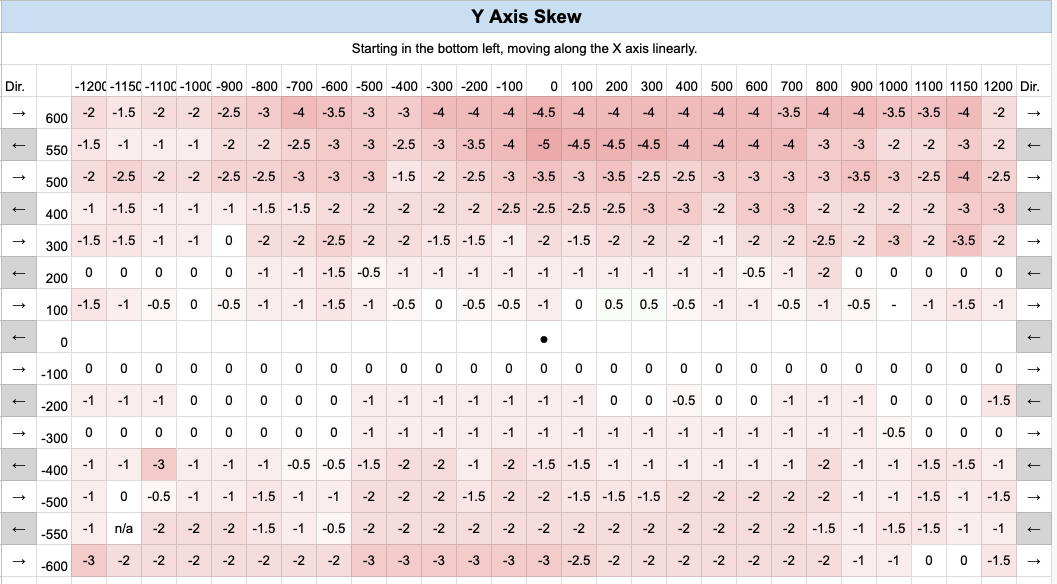
Data
I recorded the skew for each point from the origin of that row or column as signified by the blank cells. The X and Y axis skew data was recorded separately to make the visualization easier, but the google sheet has coordinates if someone wants to use that data. Here’s the google sheet
I think the big finding here is that the accuracy is almost the opposite of what the hypothetical frame calculator suggests near the edges.
What I think this data shows is that belt angle or tension of the non-pulling direction is the most important factor. Since the machine is making rows of dots on the X axis, I’ve indicated what direction it’s moving for each row. For example, with the machine moving to the left away from the right side of the board near the middle, the belts opposing the movement (TR BR) struggle to hold the M4 in place and are over powered due to the angle of the belts on the far side (TL BL) which are pulling more directly. You can actually observe this when calibrating near the edge, the machine stops and when the belts tighten it is pulled toward the center. When the machine is in one of the corners, the nearest belt has less angle and can thus hold the position much better - but again this has a lot to do with direction.
Possible solutions
Cut paths that move away from the edges should help, as well as avoiding like 2-3" along the edges.
What I think would be really interesting to play with is torque/length vectoring in the software based on the machine position. @bar mentioned here that it’s possible to adjust the tension/length dynamically. How could we go about shortening the length of the belts near the edge to compensate for this skew?
Can you explain this to me a bit more, I’m not totally sure that I’m getting it.
This part is actually pretty simple, we can 100% try this out. The function for computing the correct belt length for a given XY coordinate looks like this (different for each belt)
float Maslow_::computeTL(float x, float y, float z) {
    //Move from lower left corner coordinates to centered coordinates
    x       = x + centerX;
    y       = y + centerY;
    float a = tlX - x;
    float b = tlY - y;
    float c = 0.0 - (z + tlZ);

    float XYlength = sqrt(a * a + b * b); //Get the distance in the XY plane from the corner to the router center

    float XYBeltLength = XYlength - (_beltEndExtension + _armLength); //Subtract the belt end extension and arm length to get the belt length

    float length = sqrt(XYBeltLength * XYBeltLength + c * c); //Get the angled belt length

    return length;
}
All we need to do to adjust that is add another line that is something like length = length + 10; which would add another 10mm to the length. The tricky part is figuring out what the right math to add the correct amount for a given XY coordinate is.
If you tell me what math you want there I can generate a firmware version to try it.
It’s kinda like hanging a bucket of rocks from a string that you and your friend are holding. If the two of you are close together the force is more directly applied to the bucket, if you were like 20’ apart it would take an insane amount of strength to lift the bucket by just pulling on the string.
As for what I was saying previously:
The red arrow is the direction of movement. Angle A is the difference in angle from the direction the machine is trying to move. i.e. if the machine was moving to a corner it would be 0 for that belt. Angle B is the same thing for the trailing direction.
The first observation I noticed in data is that the skew is always negative, I think this is because the longer belts always apply force more directly due to less angle.
The second observation is that I noticed is that moving toward the center has more negative skew. I believe this is because in Figure 1 the force toward the center of the board is greater because we have angle A<B and the machine can pull harder in this direction compounding the first observations issue. In figure 2 the long belts are spooling out and the issue isn’t as bad but because A>B there’s less force in this direction (assuming the motors always pull at the same force.)
Third observation, is the corners tend to have less issue because the closest belt has less angle.
Basically if the force/tension/movement from the machine is always equal, the applied physical force is going to change depending on where the machine is and what direction it is moving.
So how do we correct for that force imbalance? Should we be computing the net force in the Cartesian directions (X and Y) and trying to balance that so we’re always pulling as hard in X as we are in -X?
So how do we correct for that force imbalance? Should we be computing the net
force in the Cartesian directions (X and Y) and trying to balance that so
we’re always pulling as hard in X as we are in -X?
I don’t think ‘pulling as hard’ is the issue, I think the problem is the belts
stretching and different lengths of belt with the same total force on them
stretch differently (and then there are the angles)
since we can’t measure force directly, I think we are going to need to try and
measure belt stretch by force/length and then calculate on the angles
Yeah basically. Seems like we’d want to have a target force in any cartesian movement and adjust the belts to meet that target based on the direction of movement and the calculated angle of each belt.
Per @dlang 's comment, I’m not certain we really need to know what the actual force is, just that each belt changes in relation to some central factor.
My initial thought was that stretching was causing this issue, but if that was the case I think we’d see the complete opposite skew.
Theoretically stretching would happen more on a longer belt and we’d see a positive skew when the machine is at the edges of the workpiece, not negative. Also, in relation to movement, in figure 1 where the machine is moving toward the center, stretching on the longer belts would mean less skew, but we’re seeing more in this direction.
One more observation, the top left quadrant seems to buck the norm of skew being worse while moving toward the center of the board on the X axis. Not exactly sure why.
My initial thought was that stretching was causing this issue, but if that was the case I think we’d see the complete opposite skew.
Theoretically stretching would happen more on a longer belt and we’d see a positive skew when the machine is at the edges of the workpiece, not negative. Also, in relation to movement, in figure 1 where the machine is moving toward the center, stretching on the longer belts would mean less skew, but we’re seeing more in this direction.
Remember, we are setting the belt length by counting the number of teeth.
This should mean that the belts are actually a little longer than we calculate
due to stretch
but there is more stretch for the same amount of force on a long belt than there
would be on a short belt
One more observation, the top left quadrant seems to buck the norm of skew being worse while moving toward the center of the board on the X axis. Not exactly sure why.
that is the top arm, so a slightly longer belt and the arm may flex down a bit
more???
It would be interesting to see if a horizontal orientation (not fighting gravity) has a similar effect.
I have put a pulley on a slider at the top of my vertical frame with a counterweight on the reverse to reduce the effect of gravity and also to prevent the M4 from crashing to the concrete if a top belt failed.
Ha! That’s a cool idea! I was thinking if we have some sort of torque vectoring maybe we could factor in the weight of the machine. I think that’s why the Y skew at the top of the board is worse – the angle of the top belts struggle to fight the weight of the machine.
The tension on the belts is the highest in the top center, but even with a wide frame that you have, this should be well clear of your work area
but one thing that you are showing is that there are problems besides the angles that we have been calculating with.
do you have access to a 3d printer? I’d love to have you print the corners for my super-simple frame and build a near-minimum size frame (~2.5 ft square) and see what having the belts level and short does for accuracy
I do have a 3d printer. I had made some spacers once so all of the belts were at the same angle and it didn’t work very well unfortunately. The sled was lifting all over the place and that’s primarily what I was trying to fix.