X & Y Accuracy Analysis: Belt Stretch

Here’s the next installment in my accuracy research for the M4, focusing on belt stretch. Breaking this out into a new thread since the previous X & Y Accuracy Analysis was getting pretty unwieldy.

Hold on to your asses, because I think we’re on to something here (especially you @dlang since you’ve been outspoken about belt stretch)

Background
If you’ve read my previous threads, I’ve been having issues with dimensional accuracy on the M4, especially when cutting near the edges of a full 4x8 sheet of material. You can read those threads to catch up on what I’ve experimented with, but after the last round of testing dimensional accuracy belt stretch, or elongation, seemed like a very plausible cause.

Process
I figured that we needed two sets of data to collect to measure stretch of the belts used on the M4:

  1. Measure isolated stretch on a section of M4 belt for a range of given forces/weights
  2. Measure what forces the belts see during normal operation (in my case, a vertical frame)

For the first data set, I rigged up a section of 100mm and 200mm from a steel door frame in my garage with a massive header block. The deflection of the top mount was only about 0.1mm measured with a dial indicator - much less than the accuracy of my measurements :stuck_out_tongue: I then made a janky mount for a ruler and used a crane scale to measure the force required to stretch the belt by 1mm increments.

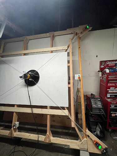
To measure the actual force of the M4 while on the frame, I installed four of these crane scales in each corner of my frame. This caused a bit of an issue with the belt length, but looking at the maslow.yaml file I noticed Maslow_beltEndExtension was set to the distance between the anchor and where the belt started. So I added the length of the crane scale to that measurement and everything seemed to work perfectly. Next, I mounted the M4, jogged to various positions, and recorded the force on each corner, including the machine hanging w/o the bottom belts connected.


Data
First, let’s start with the belt stretch. While I don’t think these scales nor my methods are super accurate, I found that these belts stretch about 1% per 5kg of force. Or about 0.2% per kg of force.

Next, what force do the M4 belts actually see? It’s important to note that a vertical frame has to also carry the weight of the M4 across the top belts. Here’s the results of jogging the machine around to various points on the frame. I found that the direction a machine arrives to a point might slightly impact the forces measured so you’ll see some of that in the data.

Results
I wanted to see if I could predict the position error I’ve been seeing on the machine and took a stab at what I usually measure, traveling from 0,0 to 1200,0. So I created a spreadsheet to calculate the belt length of TR and BR throughout this movement in 200mm increments along the X axis. I used the actual measurements from my frame size including arm length and belt end extension to model this travel, then factored in belt stretch.

Since belt stretch is a factor of applied force, which changes with belt angle, length, movement direction, and who knows what else, I used the data to create a force coefficient. From 0,0 to 1200,0 the TR and BR belts moves 800mm and the load increases by about 3kg, which gives us an increase of 0.00375 kg per mm of travel.

Now we have a stretch coefficient and a force coefficient and can calculate what’s likely to happen on the machine VS what the M4 is told to do. I used the trusty Pythagorean theorem to calculate belt length and the inverse to get back to cartesian measurements. I accounted for stretch in 200mm increments because as the machine moves the belt is locked into the spool so the length and the force change constantly. Because of this, we don’t have a linear error in X travel, but something that looks exponential.

Here’s the maths:


THIS IS VERY COOL! I consistently have measured ~6mm off of the X axis while jogging from the origin to 1200,0. Like nearly every damn time. While this is just one calc for one direction, I think this research is getting pretty close to being actionable.

Conclusion(s) and Next Steps

  1. I think this research so far validates that these accuracy issues are due to belt stretch. As the machine is pulling on a belt to travel the stretching causes it to think it’s further along than it actually is.
  2. Stretch is a factor of the total force imparted on the belt, which is caused by direction of travel, belt angle(s) and length, frame orientation, motor torque, and I’m sure some others too.

So now what? I’d still like to run some more research to see if the math checks out for machine movement in other directions. If so, then I hope we could implement some force/stretch coefficients into the software that are a little smarter than tuning esteps. The other horizon is to look at other brands and types of 2GT belts to see if we can reduce the stretching issue. I should have some arriving today and will report back. :saluting_face:

17 Likes

Loving the data. And glad someone finally used scales to measure pull force. Out of curiosity what retract value are you at?

Might be important to chart a few different values too.

Dano

Thanks! Would much rather be making stuff, but contributing to the project is fun too.

The retract force is the stock 1300. Definitely agree with more testing, especially for horizontal setups.

1 Like

Thinking about it more and one question.

Am I thinking wrong that the stretch should actually make the belt longer than expected. So should your move to 0,1200 actually be long, and I would call that +6mm. I might just have a ± sign interpreted wrong.

Dano

Yeah it’s kinda counterintuitive. Think of it like you’re in a raft crossing a river with a rope. You know it takes 100 pulls to get across the river so you count to 100 then hop off. Now think about if the rope actually stretched a bit each time you pulled on it, the section in front of you gets a little longer and now it’s going to take more that 100 pulls, so you end up short.

Same with the M4, it counts to 100 and thinks it has arrived but it’s always a little short because the belts stretch in the direction it’s moving.

3 Likes

In earlier posts, @bar mentioned they initially chose Kevlar-reinforced belts because steel ones tend to stretch.
Interestingly, though, the M4 now is equipped with steel belts.
I wonder if switching back to Kevlar would make a difference.

2 Likes

Interesting… @bar can you help me figure out the correct Kevlar belts to try? The ones I ordered weren’t the right size, but that was a bit of a gamble any way.

1 Like

Kyle wrote:

To measure the actual force of the M4 while on the frame, I installed four of
these crane scales in each corner of my frame. This caused a bit of an issue
with the belt length, but looking at the maslow.yaml file I noticed
Maslow_beltEndExtension was set to the distance between the anchor and where
the belt started. So I added the length of the crane scale to that measurement
and everything seemed to work perfectly.

That’s exactly the sort of think that this was added to support :slight_smile:

fantastic work.

David Lang

2 Likes

6mm wide gt2 belts should be the right thing to use.

David Lang

1 Like

The belt I ordered from Amazon appear to not be 6mm GT2 belts but look more like 4mm. So I reached out to Gates directly to see what options they have with the lowest elongation factor that will work. Their website has a ton of products and it’s difficult to tell what is what.

1 Like

Starting to figure out the Gates catalog and seems like LL2MR06 is the correct belt. I accidentally ordered the 4mm version.

Update: McMaster-Carr has them but not in a long enough section. So I just ordered a 1000mm section of the 6mm GT2 to test and another of the 9mm wide. Figure if the 9mm wide performs a lot better, it probably wouldn’t be too crazy to modify the machine to make it fit.

2 Likes

That’s super interesting data @kyleschoen. As soon as I get the Maslow steel belts I will compare them to the Kevlar ones. In my preliminary tests i saw about 3 times less stretch than you do. Seems like the Kevlar belts indeed do stretch less.

1 Like

I just ran the math as well and that looks very promising. Are the belts you tested 6mm wide as well?

Would still love to have you copy/paste your results here to keep the elongation/stretch dialog in one place.

1 Like

Copy Pasted my original Post here to keep everything in one place:

I thought I’d share some early results from preliminary traction tests I’ve been doing to optimize the test setup.

For now, I used some random 3D printer belts I had lying around. Judging by their construction, they appear to be Kevlar-reinforced. I’m still waiting on the steel-reinforced Maslow belt that Bar kindly sent me—I’ll test that as soon as it arrives.

Test Setup


The grips aren’t ideal for this kind of testing, but so far, the belts aren’t rupturing within the grips and there’s no noticeable slipping, so I consider the data usable. The extensiometer I used is also not the most suitable one for this setup—it introduces a bending moment that adds some error. To reduce this, I preload the belt with 50 N before attaching the extensiometer. The values between 0–50 N are extrapolated under the assumption of linear elastic behavior. From there, I stretch the belt at 2 mm/min until it breaks.

Results

The x-axis shows elongation in %, and the y-axis shows the load in Newtons. On the right are some key outputs:

  • Fmax
  • Slope of the linear part (E)
  • Elongation at rupture (A)

At first glance, the behavior appears quite linear up to failure, and the three tests yielded very consistent results. The belts ruptured between 5.2% and 5.5% elongation, with a slope of approximately 170 N per 1% elongation—meaning the belt stretches by about 1% for every 170 N of applied force.
One small kink appears in the data at around 4% elongation. This is an artifact caused by the removal of the extensometer just before failure to avoid damaging it. As a result, the actual elongation at rupture is likely slightly lower than recorded. For calculating the elastic constant (E), only the data prior to this bend was used, so this artifact has no impact on the slope estimation.

Break Images


In every test, the Kevlar strands broke all at the same location.

6 Likes

Yes, I forgot to mention. Those were also 6mm wide GT2 belts.

4 Likes

Plugging @Lais data into my spreadsheet shows a great improvement on the calculated 0,0 to 1200,0 movement. Again, I need to fiddle with calculating other directions, but I’d be okay with 1-2mm off out at the edge of the workpiece for now. I bet we can improve on that with some software adjustments or reduced retraction force.

3 Likes

Genius :heart:

This is much higher than I would expect!

This is super exciting!

The code for this shouldn’t be too tricky, it’s just a mater of finding the right values to put into the code that’s hard

I think I had that backwards, at least according to the datasheet the steel ones are supposed to stretch less. That being said 100% don’t take my word for it. Let’s double check that!

something to keep in mind for longer term testing, the tension when moving may
vary based on how fast you are moving, if vertical what the tilt is, how
slippery the sled is to the workpiece, and the cutting forces needed (how deep
is your cut, how big is the bit, and how dull is the bit)

some of this is unknowable, but we may be able to get something much better than
what we currently have.

David Lang

I’m not super familiar with the belts themselves, but from having a google around at belts and my own vague knowledge of composites, i’d caution to make sure you know what each belt is actually reinforced with.

I’ve seen kevlar, aramid and fibreglass reinforced belts touted, and which it is likely matters.

Kevlar is an aramid, but a specific, high specced one. They both should have significantly less stretch than fibreglass.

It wouldn’t surprise me if testing showed that stretch went:
Kevlar < generic aramid < steel < fibreglass

And lumping them all together could be where steel-re-enforced vs fibre-re-enforced confusion could creep in.

Though that’s 100% speculation based on what I remember from board repair - and for example just the amount of re-enforcement in different models of belts could vary it too - so take it with a pinch of salt.

Yeah, without directly measuring belt tension, implementing any correction model would be tricky. In theory, if you know the belt’s elastic constant, you could correlate motor current to tension with some calibration, but I’m not sure the constant is consistent enough between batches or over time to make that practical. Either way, minimizing error at the source by using stiffer belts is definitely a path that should be explored.

1 Like