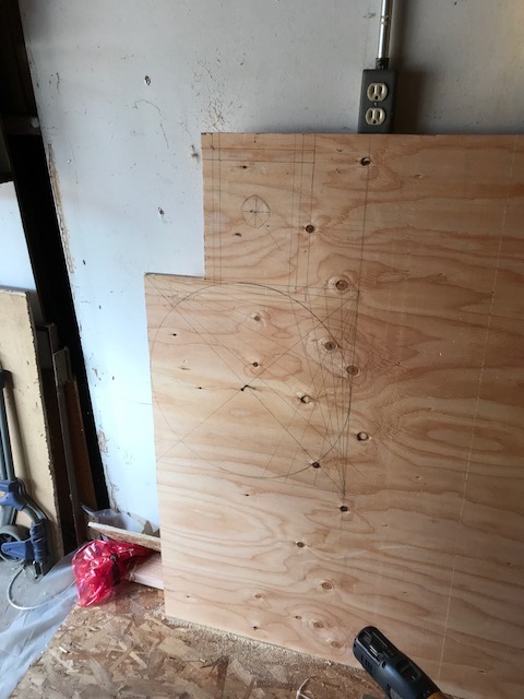
This is the bracing - it required 1 extra 2x4 x8ft.
Notice it’s a Y shape with a cross brace at the top.
The rest of the wood there shown is the 2x4 x 10ft 's cut for the final build. Once I’ve got to cut my sled I’ll document everything. The exact locations and the sizes.
Yes, both Logan (@pillageTHENburn) and I have posted links to our design files. If you can give me
to the weekend, I’m going to see about doing a wiki page on the different
designs.
We have different frame designs, and different sled designs, and finding the
details in 700+ thread forum threads is not easy.
Here’s an early post with a chart that shows the 4 original concepts and which measurements are important. The drawings on the chart are just for general reference, they are not to scale. It explains most of the critical relationships between different bars in the linkages.
Here’s my original test drawing of a top mounted design:
And here’s David’s improvement on that design by using cut-outs for chain clearance. Note that the actual lengths of the bars is not critical as long as they clear your router. The critical part is that they are consistent with each other. The distance between the top hole and center hole in the vertical bars must equal the distance between the top and bottom mounting points on the sled AND the distance between the center hole and the chain mounting hole in the vertical bars must equal the distance between the bottom mounting point on the sled and the center of the router bit. The length of the “horizontal” bars will dictate how where that red dotted line is, this is the point that the tip of the chains will trace in space. All 4 horizontal bars must match each other.
Similar rules apply, parallel bars need to be the same length as each other. Lengthening the pivoting bars will move the red dotted line. Lengthening the two 45˚ bars (the bars that the chains attach to) will buy you more clearance for the router. The chain mounting point does not have to be in the center of the bar, but it must match the distances between the sled mounting points and the router bit (4.5" in this drawing).
Both designs use the same principal of a parallelogram to trace a concentric circle around the router. The biggest mechanical difference between the two is probably that the joints in the top mounted design are under both compression and tension and joints in the 45˚ design are all under tension.
Next time you have this out on the driveway, would you mind posting a photo that shows this bracing head on? I’m about 1 day behind you in my build and I’d like to add some bracing as well.
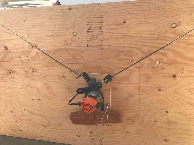
I did a little cable management at the end. I need to counter sink some bolts and I need screws to mount the router. I also need to mount the Z axis. Progress is being made.
BTW Does anyone have ugraded/‘pirated’ Ikea designs? Would be cool if we could improve upon the swedish designs and eventually share it back to them in an open repository.
I hear IKEA is in the process to let the customers scan their shopped items DIY style rendering jobs obsolete for the cashiers. So maybe we can make it more easy for them and just build some of their furniture at home. Then they don’t even have to produce it any more.
O dear, I went sideways on the topic.
BTW The $5 holesaw set is a great find. If I get near an Ikea i’ll try to remember this tip.
So I made lots of progress today. I have the basic setup and calibration done. In theory it is ready to cut. Monday I will add the Z axis. Then switch to working on the final sled design. My linkage should be on it’s way today. I also have an idea for a triangular sled design.
I did have about an hour of my day go out the window due to a faulty powerstrip. Once over that speed bump it was smooth sailing.
I added a Parts/Shtuff holder & a Pencil holder.
Once I’m done I’m writing a book. I have a grip of little tips to make it easier to build.