lets have a conversation about 2x4’s and fastening systems. For my non US peeps please alter to MM in your head. I’m going to toss a premise out. If anyone wishes to argue or dispute it I will be glad to participate as long as you create a new thread where we can debate it. For the sake of argument we are going ot say a 2 x 4 is resistant to bending more on the edge of the 2 x4 rather that the 4x2 edge due to bias.
One of the figures below shows this -
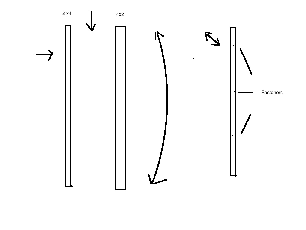
Further when you introduce fasteners you are attempting to crush or expand the material between the fasteners agins it’s shear strength making it avoid flexion more between the points of entry of the fasteners.
Let’s talk about floppy - if you take a playing card and hole it corner to corner diagonally between your thumb and pinky then squeeze, you are simulating the load stress on a 4 x 8 sheet of plywood.
If you tape a toothpick diagonally in the same direction on the card as the force from thumb to pinky it will be much more rigid.
Using this axiom I use the 2 inch side of the 2 x 4 to introduce stiffness. It will require 1 more 2 x 4 x 8ft board.

I started with a saw horse and a concrete block to give it weight to hold the 4 x 8 plywood resting against it. I set the Plywood leaning against the sawhorse and used a 18 inch 2x4 against the plywood against the 4 inch side to keep it from creeping down as I worked on it.
Next I took the 39 & 3/8th boards and marked them at 20 inches and installed them on 45 degree angles as in the standard build. I then user the 53 inch boards at the bottom in place of the 18’s.
I used an 1/8 bit to pre drill my paths then star drive deck screws. Deck screws like this have multiple points of contact so almost never strip, they have a coating to improve driving them and corrosion, they also are self countersinking.
Now to stiffen the build I added a 2 x 4 x 8ft I had laying around on a diagonal from a lower corner to the upper arm. I secured it in 4 points across it’s path with deck screws. Next I used a 57 inch 2 x 4 in the opposite diagonal and again used 4 points across it’s path to foam a Y shape. I thne bridged the top horizontally with the other 57 2 x4 creating a triangle pattern and secured it with 4 fasteners. Last I put the other 18 inch piece in place to secure the new structure for when it was leaning on the sawhorse in the middle.
see the pictures below -


Let me know if you have questions - the purpose was to use as much of the cut parts waiting for the Final frame to make the Temp frame stiffer.


