Belt loose / e-stopping / G0 maybe?

Pulled from Z- axis - 2 bad boards? 2 bad motors? Or something funky?
as it doesn’t appear board related. This is my original message, more to follow after

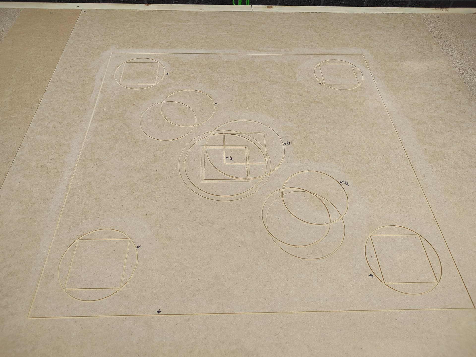
I set myself up a calibration image:

900_900

(It’s an SVG and interestingly krabzcam got the inside/outside wrong for the circles - i assume it’s doing it off normals or something so could be how I created it).

I only had it do one layer, and the generated code is:
900_900.nc (6.3 KB)

The order it cuts is:

Now, it repeatedly failed when trying to do move (3):
Maslow-serial.log (3).txt (24.0 KB)

The BR belt went slack, then would stop, final few messages from above:

[MSG:WARN: Position error on Bottom Right axis exceeded 15mm while running. Error is 15.263mm Counter: 3]
[MSG:WARN: Previous error was 15.263mm]
[MSG:WARN: Position error on Bottom Right axis exceeded 15mm while running. Error is 15.025mm Counter: 4]
[MSG:WARN: Previous error was 15.025mm]
[MSG:WARN: Position error on Bottom Right axis exceeded 15mm while running. Error is 15.113mm Counter: 5]
[MSG:WARN: Previous error was 15.113mm]
[MSG:WARN: Position error on Bottom Right axis exceeded 15mm while running. Error is 15.219mm Counter: 6]
[MSG:WARN: Previous error was 15.219mm]
[MSG:ERR: Emergency stop! Stopping all motors]
[MSG:WARN: The machine will not respond until turned off and back on again]
[MSG:INFO: Reset during file job at line: 49]
[MSG:ERR: Position error > 15mm while running. E-Stop triggered.]

The relevant bit of the gcode:

I51.85212539 J-51.85214489 X600.01873767 Y373.27911215 F600
G0 Z3
G0 X300.34852112 Y672.94932869
G0 Z0
G1 Z-1.5 F400
G2 I-0.08965265 J-73.42065099 X352.17515646 Y651.4449475 F600

The I is the end of the circle, I believe it fails in G0 X300.34852112 Y672.94932869 (which seems perfectly valid).

Other possibly relevant stuff:

  • Was running router and vacuum (more on this later).
  • It was repeatable - it happened in the same place 3 times.

So, I took apart the Maslow and:

  • BR spool wasn’t binding
  • The magnet appears to be well seated.
  • I swapped BR with TL.

Now, it starts to get interesting.

With:

  • The router and vacuum off.
  • Raised 10mm from home (so the bit didn’t catch).
    It successfully traced the whole file.

BUT, with:

  • The router and vacuum on.
  • The normal height (so bit cutting)

It failed doing 4 (ignore the curve, it was straight, that’s to make it clear on the diagram):

Which looks very much like 3 but in the opposite direction. Annoyingly, I didn’t have much testing time today, so I haven’t repeated yet.

Maslow-serial.log (5).txt (11.5 KB)

[MSG:WARN: Position error on Bottom Left axis exceeded 15mm while running. Error is 15.208mm Counter: 3]
[MSG:WARN: Previous error was 15.208mm]
[MSG:WARN: Position error on Bottom Left axis exceeded 15mm while running. Error is 15.305mm Counter: 4]
[MSG:WARN: Previous error was 15.305mm]
[MSG:WARN: Position error on Bottom Left axis exceeded 15mm while running. Error is 15.008mm Counter: 5]
[MSG:WARN: Previous error was 15.008mm]
[MSG:WARN: Position error on Bottom Left axis exceeded 15mm while running. Error is 15.112mm Counter: 6]
[MSG:WARN: Previous error was 15.112mm]
[MSG:ERR: Emergency stop! Stopping all motors]
[MSG:WARN: The machine will not respond until turned off and back on again]
[MSG:INFO: Reset during file job at line: 61]
[MSG:ERR: Position error > 15mm while running. E-Stop triggered.]

Again it was the same arm (now swapped to TL) that went slack, but interesting it was BL axis showing the error.

Another thing I noticed - when it did the successful pass, when moved back to home, it was out of position:

0.23 seems not super significant, I am not sure about 0.96 - though I guess 1mm off vertically after travelling all that distance is probably fine.

Next steps

Any thought’s appreciated, but equally, given it’s on a suspect board, this might be resolved by a board swap, so it just becomes an interesting data point in that case.

So avenue’s for investigation:

  • New board - do I still see it.
  • Router on, but no vacuum / no bit (ie, is it interference from the router and/or extra load of cutting when running a Y cable).
  • Router on, vacuum on, no bit (as above with vacuum).
  • swap magnet and/or sensor board between arms.
  • swap magnet and/or sensor board for new.
  • swap motor between arms.
  • swap motor for new

In the order I think is most likely. Not sure what order i’ll investigate, depends when I get the new boards vs having time to play with the Maslow.

One thing I do need to work out though is if I can source the magnets locally? Are they readily available? I have spare rollers and a spare sensor board, but I don’t have spare magnets (or a spare motor).

I did wonder if the magnet could also be shimmed to sit nearer to to sensor as a test too.

Ok, so the update for this - more testing shows some interesting stuff.

I re-ran with router-on, no-bit-no-vacuum. I still saw the issue.
I re-ran with no router on and it failed once, and succeeded once, or more accurately seemed to recover once.
I was able to tweak some stuff and get a full cut (and a decent level of accuracy):


(the second is sanded to remove the cut fluff, and the black arrows are to tell me which ones at from this cut).

So, i’m now slightly suspicious of what’s happening with the G0 movement.

When it succeeds these fast-diagonal-G0 commands, what seems to happen is:

  • The trailing belt goes slack right at the beginning of the move.
  • It zooms off with the 3 leading belts tight and pulling.
  • The trailing belt slack pulls in as it reaches the end of the move.

The only difference with the failing ones is it appears it happens to move about enough because of the slack that the ‘Position error’ is triggered.

Now the interesting thing is - I tweaked my file so the G0s were all replaced with G1s with feed rates. Nothing crazy, I tried F600 and then F1000, so (third line):

I51.85212539 J-51.85214489 X600.01873767 Y373.27911215 F600
G0 Z3
G0 X300.34852112 Y672.94932869
G0 Z0
G1 Z-1.5 F400
G2 I-0.08965265 J-73.42065099 X352.17515646 Y651.4449475 F600

became:

I51.85212539 J-51.85214489 X600.01873767 Y373.27911215 F600
G0 Z3
G1 X300.34852112 Y672.94932869 F1000
G0 Z0
G1 Z-1.5 F400
G2 I-0.08965265 J-73.42065099 X352.17515646 Y651.4449475 F600

And the belts stayed tight throughout the travel, and i was able to do my full test cut above, router on, vacuum on.

I haven’t delved into the code yet, but I wonder:

  • Is this expected behaviour of the G0 command - perhaps because it’s a fast move we slack the trailing belt?
  • Should the ‘Position error’ check be disabled at the beginning of G0s, and re-enabled at the end?

I need to spend some time ramping up the travel speeds with G1s to see what happens and look into the code for G0s, but it’s interesting. And none of this explains why a specific arm seems to be the trigger for it, but I wonder if it’s sliiiiiiiightly more stiction-y than it’s opposite so more prone to this for some reason.

1 Like

Other possibly relevant stuff:

  • Was running router and vacuum (more on this later).
  • It was repeatable - it happened in the same place 3 times.

So, I took apart the Maslow and:

  • BR spool wasn’t binding
  • The magnet appears to be well seated.
  • I swapped BR with TL.

Now, it starts to get interesting.

With:

  • The router and vacuum off.
  • Raised 10mm from home (so the bit didn’t catch).
    It successfully traced the whole file.

BUT, with:

  • The router and vacuum on.
  • The normal height (so bit cutting)

It failed doing 4 (ignore the curve, it was straight, that’s to make it clear on the diagram):

This sounds like a static electricity problem, with dust blowing through the
hose it builds up a static charge and confuses an encoder. double check that
encoder and it’s wires, and see if you can get your hands on a conductive holse.

with the 4.0 we were having this a lot and bar wasn’t, he did some testing and
found that with the expensive festool conductive hose he didn’t have a problem,
but with a cheap hose he did.

One thing I do need to work out though is if I can source the magnets locally? Are they readily available? I have spare rollers and a spare sensor board, but I don’t have spare magnets (or a spare motor).

note that the issue is normally not that the magnet isn’t seated, but that it
can rotate.

these magnets are available, but you need to look for a magnet that’s radial not
axial (i.e. N and S poles are on the side of the magnet, not the top and bottom)

I did wonder if the magnet could also be shimmed to sit nearer to to sensor as a test too.

that’s not likely to help.

David Lang

very interesting. what CAM software are you using? somewhere in the machine
definition there is a feed rate for G0 defined (@bar any chance this is set in
fluidNC???)

if that feed rate is too high, the maslow can’t keep up with what it’s being
told to do and that could result in where it things it should be not matching
where it is.

the PID loop will eventually complain about excessive motor current (4000 IIRC)
but it could be that the PID loop isn’t ramping up fast enough and it’s hitting
the position error first.

figuring out how fast it’s trying to move for G0 and then lowering that seems
like a good thing to do.

David Lang

At the moment - KrabzCAM, though I might switch to something else.

Having a quick look in FluidNC it has max rates for X and Y separately of 2000. And a max acceleration for each.

I don’t think it’s a coincidence i’m seeing this on a 45 degree move - that would give me the greatest combined actual move after all. It seems like a possible holdover from gantry CNCs to just consider X and Y separately.

If I want to stick to 2000 speed, I think I need to dial it back to about 1400 for the hypotenuse / combined vector to be under 2000 :thinking:

So i’ll give 1400 for X and Y a go with the G0 file when I next get a chance.

I think that this is a PHENOMENAL test. You did a really really good job of identifying exactly the issue I’m pretty sure.

This is exactly what is going on. The G0 command basically tells the machine to move “as fast as possible”. The question then is “how fast is that?” If we tell the machine to move 9999999999mm/s it’s obviously not going to actually keep up and then we get that error message.

We can set the speed limit in the settings like this:

(I’m pretty sure that will set the limit)

The problem is that those settings were designed for a traditional XY machine where we know the max speed in X and Y…unfortunately the max speed in X and Y for Maslow is going to be different depending on the frame size and also where on the frame we are.

I think that maybe the real solution is that we need to set a max speed per belt, but that’s going to require some significant changes to how we interface with FluidNC.

1 Like

Dave wrote:

Having a quick look in FluidNC it has max rates for X and Y separately of 2000. And a max acceleration for each.

I don’t think it’s a coincidence i’m seeing this on a 45 degree move - that would give me the greatest combined actual move after all. It seems like a possible holdover from gantry CNCs to just consider X and Y separately.

If I want to stick to 2000 speed, I think I need to dial it back to about 1400 for the hypotenuse / combined vector to be under 2000 :thinking:

I don’t think there is anything special about that 2000 speed, I think it’s
probably the fluidNC default, so it may be that we need to dial it back further
for the maslow.

David Lang

2 Likes

Yeah, 2000 does sound like an arbitrary default!

Though it did occur to me as another relevant question - when I set a Feed of n, is it calculating the vector so that it’s n, or is it doing limiting the X travel and Y travel to n each? I assume it’s calculating the vector to be a travel speed of n.

So i’ll try my diagonal G1s at 2000 I think as a next test and see what happens!

1 Like

Dave wrote:

Though it did occur to me as another relevant question - when I set a Feed of
n, is it calculating the vector so that it’s n, or is it doing limiting
the X travel and Y travel to n each? I assume it’s calculating the vector to
be a travel speed of n.

it is calculating the travel speed along the path

So i’ll try my diagonal G1s at 2000 I think as a next test and see what happens!

and also try them at 3000 (~2000 each in x and y)

also note that the load on each arm will be different in different locations

@bar, what is the rated speed of these motors under load?

David Lang

2 Likes

They’re rated for 50rpm I believe, but how much distance that translates too will depend on the amount of belt on the spool…although we can just make a conservative estimate of assuming no belt on the spool.

1 Like

Bar wrote:

They’re rated for 50rpm I believe, but how much distance that translates too
will depend on the amount of belt on the spool…although we can just make a
conservative estimate of assuming no belt on the spool.

ok, 50 rpm X 11 teeth on motor / 82 teeth on spool x 2 x pi x 44.5 radius= 1875
mm/min

we should probably derate this in case there isn’t full voltage/current
available, so a max of 1500mm/min (40 rpm) is probably a safer number to plan.

David Lang

That seems like a pretty big handicap to put on the machine. I pretty regularly cut at 2000mm/min without issues.

Keep in mind that for a most XY movements we can go much faster than that because of the way the belts relate to movement in the XY coordinate system.

FluidNC has some built in kinematic that I think we need to be using to make it so the system can set a per belt max speed instead of a per XY direction max speed. I bet if we do that we could actually move quite a bit faster

Bar wrote:

That seems like a pretty big handicap to put on the machine. I pretty regularly cut at 2000mm/min without issues.

Keep in mind that for a most XY movements we can go much faster than that because of the way the belts relate to movement in the XY coordinate system.

you may tell it to move at 2000mm/m but does it really move that fast?

the worst case is that it is moving directly towards one anchor and directly
away from another. In that case, the max speed is limited by the belt speed

did I make a mistake on the math or on counting teeth?

FluidNC has some built in kinematic that I think we need to be using to make
it so the system can set a per belt max speed instead of a per XY direction
max speed. I bet if we do that we could actually move quite a bit faster

If someone has done cable driven robot kinematics, that would be fantastic to
use.

combine that with the work that someone said they were working on to make an
encoder/motor combo look like a single motor to fluidNC and most of the maslow
specific stuff can go away.

David Lang

You are right that directly towards the anchor point is the direction that we can move the slowest.

I think that in some other directions (or example directly in either X or Y direction) we can move many times faster and we should be taking advantage of that. It would be awesome to be able to jog at 6000mm/min if it’s an option.

This is similar to a problem I had earlier and confirms diagonal movements with G0 suspect:

Sending the M4 sideways & then up fixed the problem for me. I think it must be related to the M4 belts not being able to keep up when processing G0 diagonals

2 Likes