Received my maslow in the last shipment and have been tinkering with it ever since. I’m trying to do some wikihouse stuff and have come across something that is completely blowing my mind.
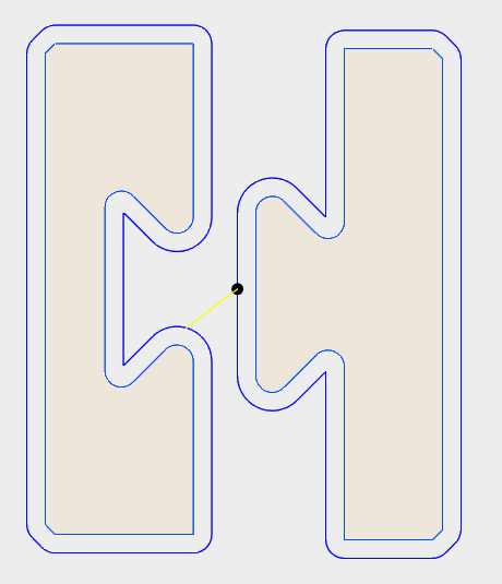
Whenever I try to do a puzzle piece like joint the piece that goes inside the other is way larger than it should be. I’m using fusion 360, I have double checked the measurements probably 1000 times and they look good. I’ve looked at the simulation in fusion and it seems perfect. I’m still thinking this is some issue with what i’m doing in fusion more than the maslow at this point, but since i’m completely out of ideas anything would be much appreciated!!
I was going to attach some files but since i’m a new member i’m not allowed to, sorry! Here some information that might be useful?
Ive also done some work on this too
When I get Back tonight
Ill post a photo, G code file and DXF File of my joint I created,
I used fusion 360 cad and cam 6mm bit
The joint close fitting and a mallet is used to hit them in
and a section on ply of is over lapped the joint to reinforce,
The G code is for 1/8 bit with a bit extra depth to go thro the ply,
i dont use Tabs as I pause g-code after one pass to trace the parts out
with the parts marked out I then fire a nail gun with brads to hold it in place
and continue with the G-code
So Run the G-code to see is it works
Is and if you wish Ill do some Instruction
I’m actually doing the WREN tolerance test current and that doesn’t actually contain those joints (are those the ones that connect the roof part of the frames?)
the only issues I can find before I run Gocode on my maslow is that the is on the cam settings
1, Height Settings
Your Ply thickness is 1/4
but Bottom Height, Stock top setting is only 0.1in and should be -0.27 a least to go thro your ply
2, On the Passes Setting
you have rough final ticked
I would un-tick this
And also tick “use Even Stepdowns”
As a preference I use a 1/4 Router Bit,
So tonight I will create a new Gcode from the Amendments and run it on my Malsow , and see how it comes Out
Yeah sorry, I probably should have said something about this earlier. This is a test one so i didn’t really want to wait for it to cut all the way through the wood so I only went 1 step down.
I will have to try the rough final unchecked.
@Jamtek Hey, thanks for looking into that! I don’t really have any tolerances setup besides the default in fusion360 (i can’t remember what it is) but if it’s all the same I would still expect the pieces to be far more similar than they are. Unless I’m misunderstanding?
But in the CAM side, I believe you have to add a clearance. I did a sketch offset of -.25 mm on the male puzzle piece contact edges and then did a push pull all the way through to cut it out of the model.
Im going to have to disagree with @Dru on unchecking ‘Rough Final’ in the CAM setup. Milling a profile on plywood probably would not benefit from a finishing pass and will add extra steps to your gcode, but I could be wrong. Im fairly new to CAM and Fusion myself, hope this helps.
Also, my want to check out Lars Christensen You Tube channel. He has covered the topic of clearances in a number of videos.
I created a public link from my Fusion 360 account, you should be able to download it, let me know. Also I extruded it to 18 mm, you will need to adjust to your stock, also did not do anything on the CAM side.
Thanks @Jamtek I will check out what you did and try and run it through some 1/4" ply! It is still odd to me that the piece matches exactly like you said but the measurements were literally .1355" (at the largest part) off from each other. I’ll let you know what i see though! Thanks again!
@Jamtek i just cut it out and besides a little wonkieness I think is more because my sled isn’t slick enough it worked out great! thanks! I guess i thought their tolerance test was accounting for this! So for offsets I will be making one side all have a bit of an offset. THANKS A TON!!! I was super confused!