For Noobs, like me, who are struggling with the software parts, please share what your workflow looks like.
I’m interested in making some flat pack furniture myself but it would be cool to see workflows for engraving and anything else you’re making!
For Noobs, like me, who are struggling with the software parts, please share what your workflow looks like.
I’m interested in making some flat pack furniture myself but it would be cool to see workflows for engraving and anything else you’re making!
This is a great question. I think there are several guides to workflows in the wiki section of the forum that would be worth while. I wrote one of those on using inkscape. I use coreldraw sometimes to make svgs or I use inkscape. Then I use inkscape to generate gcode. I’ve been looking at easel for gcode generation because the inkscape extension is very time consuming to do well, but haven’t switched yet because it is easier to trust what i know. If I move to easel, I would use coreldraw and then easel. I’ve been wanting to learn freecad and blender to do the full design -> gcode, but freecad keeps crashing and I’ve been doing other things.
I want to try Easel and also Fusion 360 but unfortunately Fusion is a bit more than my PC can handle.
Right now I’m just starting out using found svg files and MakerCAM or JSCut to generate gcode.
For me it’s the most difficult part of the process. I wish there were a place where we could download gcode for Maslow.
Ex. If you used 1/4" bit put that in a read me file and grab the gcode and run it.
I think the key is to be aware of what is fundamental, and what is not. The fundamentals won’t change, and the software is just a tool for dealing with the fundamentals in a convenient way. Then, you choose the tool that works best for you.
So, fundamentally, the target is G-code. Maslow understands a specific set of G-code commands to move the cutter around the workpiece. You can read about them here:
If you send an unrecognised code then Maslow will ignore it. If you want to do something that can not be expressed in G-code then Maslow can’t do it. At its simplest level, G-code allows you to instruct the machine to set the cutting height of the tool (Z) and move to a certain X-Y point. If the tool is above the surface of the workpiece then no cutting is done. If the tool is below the surface of the workpiece then it will cut the material. That’s it.
This leads on to physical considerations: what material is it? how deep can you cut while moving the tool? how fast can the tool move? G-code doesn’t care about this, but these factors must be accounted for when producing the G-code itself. The machine executes the G-code as best it can, but it has no way to know what material is actually present, or what tool has actually been installed, or where the edge of the material is, or how thick it actually is. The machine is blind and does what it is told to do.
So, how to produce the G-code? Well, as you can see, it’s a sequence of commands. You could write it in a text editor. If it’s a simple shape, such as a square, you could write a series of G-code commands to lift the Z axis (so the machine won’t cut), move to the start X-Y position, lower the Z axis (so the machine will cut), move to the first corner, second corner, third corner, and back to the start, then lift the Z-axis again. Remember, when you specify the X-Y positions to add or subtract half of the diameter of the cutting tool so that the edge of the cutter is on the line that you want to cut. Obviously the file is no good if you want to use a different size tool, so you’d have to regenerate the G-code with new numbers.
Doing it by hand is tedious (but a worthwhile exercise), and probably you’ll have a fairly complex shape, so you’d use a CAD (Computer Aided Design) tool. This lets you draw what you want, and you’ll end up with a bunch of elements that need to be cut. You need a CAM (Computer Aided Manufacturing) tool to take the graphic elements in the CAD drawing and produce G-code to drive the machine. The CAM tool lets you specify parameters like speed of movement, tool sizes, cutting heights/depths, inside/outside/centre cuts, and allows you to produce a G-code file for that design for that machine and that tool. The same file may work on another machine, but it might not. It also won’t produce the desired result if you don’t set up the machine properly when you start the job.
In general, the workflow is:
Idea -> CAD -> CAM -> G-code -> machine
For me, I generally use QCad for CAD, and DXF2GCODE for CAM. So, that’s two separate programs. Some CAD programs have CAM built-in, so you can produce G-code directly.
When you produce G-code you generally have to specify the machine that you are going to use. This makes the CAM software use only G-code commands that the machine is known to support, and avoid the ones it doesn’t. If ‘Maslow’ is not listed in your CAM software (and it probably won’t be) then try ‘grbl’. After you have produced the G-code you can look at the file and verify that it contains only commands that Maslow supports, and that the sequence of commands looks sensible. You can also run the G-code on a simulator, that will visually show the cutting paths contained in the file.
Even if there was a place where you could download G-code for Maslow I’d suggest you couldn’t trust it. You’d have to double-check the cutting area, tool size, feed speed, inches/mm, etc. G-code is the worst way to distribute a design.
Because Internet connectivity where I live isn’t always …
I’ve gone with the following:
I also wrote my own GCode ‘cleaning’ software. Which has an option to annotate each line in the GCode to explain what it does.
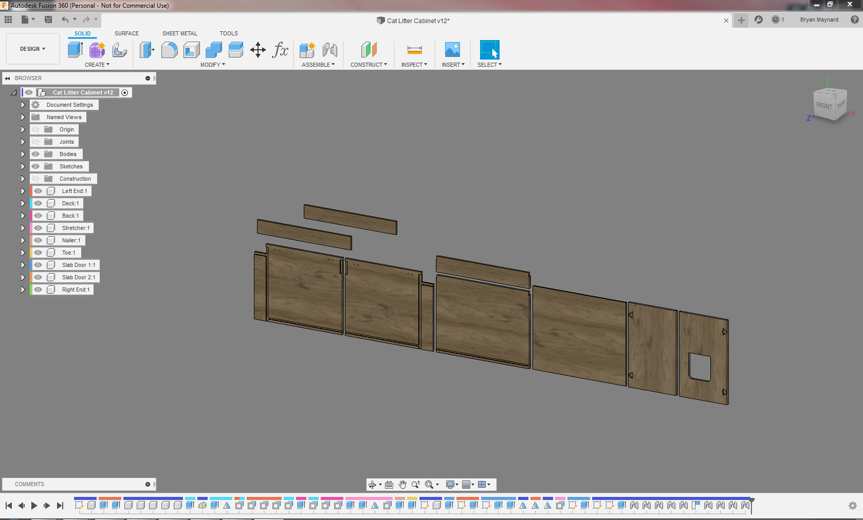
I primarily make furniture with my Maslow. I use Fusion360 for everything. My process is as follows:
User Variables:
End Section:
Doors:
Slightly different cabinet, but based on the same section. I just made an entry hole for my cats:
Next I go through the CAM workflow. The idea here is that you make a setup for every different sheet of plywood you would run. I was trying to use up a bunch of scrap, so this is actually several pieces. In your setup, you define your machine, origin, and workpiece dimensions.
After making a setup, I then go and add in all my toolpaths. I have a particular order of tooling, typically it goes drill(s), engraving tool(s), large endmill(s), small endmill(s), and then ball mill(s). That being said, when possible, I try to limit my programs to 1 tool. This eliminates the need for tool changes, and you can pretty much just let the Maslow cut it in one go. In this case, there is a drill step on the sides and doors, and everything else is cut with my workhorse 1/4" single flute bit. I start with dados and other shallow pockets. Then I do through pockets (if any). After that it’s inside contours, followed by outside contours. All of my default toolpath strategies are saved into Fusion, so I don’t have to spend long messing with the settings. I just pick my paths, locate any tabs, and I’m good to go. This cabinet took me about an hour to program. This stage can get much longer with more complicated setups or parts that require a lot of machining
I do go into more detail with toolpath settings in this post: Fusion 360 confusion - #9 by MeticulousMaynard
Cabinet side programmed, you can see all the other setups for each piece of plywood I’ll be running:
Post this. Again, with my machine setup, it knows what post processor to pull and where to output my file. I use the Maslow post processor, and it’s given me great results. I output to a dropbox folder so I can easily access it on my Maslow.
Boot up the Maslow. Load on the first piece of material and secure it. When I have larger sheets, I like to use my quick pinch clamps, but with smaller pieces I’ll get out my nailgun and brad it in place where it won’t be near the bit. I open the needed program in Ground Control
Older setup, but it’s the same idea:
Home! I move the machine to where it needs to be to set the work origin based on my CAM and set that as my home. If needed, I’ll touch off my first tool. At this point, I’ve spent 15 min tops at the machine.
Run! I run my machine with a dust collector, so I turn that on just before telling it to start cutting. Typically, the run times can be for a significant chunk of time, so rather than sit there the whole time I usually find another task to do in my shop. I never leave earshot just in case something doesn’t sound right, but my machine has been fairly reliable in the sense that I can just let it do it’s thing and not need to intervene. I have certainly sat there and watched it work for more than I would like to admit, it’s just so mesmerizing to watch.
Clean up. I park the machine, then vacuum up the mess that fell to the floor. I cut all my tabs with a hand saw and then clean them up on a belt sander. I will usually test fit all my parts to make sure all my CAD was in line with reality. From there, all the parts will need a light sanding before finishing them. I start at 120 grit and go the 220 or 320 depending on if I need to or not. This can take as little as a half hour, but the light sanding step can take quite awhile if you have a complicated assembly. A random orbit sander helps massively if you have a lot of square footage to cover.
Finish. This should be pretty self-explainitory to most woodworkers out there. I like to use Tung Oil, unless staining is required. Tung oil is an requires 2-3 coats, each one takes about a day to set.
Sanded and oiled cabinet parts for my kitchen (Doors thrifted, not Maslow’d):
From there, you would install the cabinet. Hopefully this isn’t just a wall of text to readers. I wanted to be detailed enough but also be concise. It’s a hard balance to strike. Sorry for jumping around on these pictures so much, I haven’t documented my entire workflow on just one job, so I had to pull from a few similar ones.
Happy chip-making everyone! 
Thanks for the screenshots. Very helpful.
I have parts on order to upgrade my PC Memory and Video Card so it can support fusion 3D.
Do you share your furniture designs anywhere? I’ve just moved for work and invested in the Maslow so I could build new furniture. I couldn’t afford to bring my old stuff w/ us.
The best place to find designs from the forum is on http://maslowcommunitygarden.org/. There are a few of my designs on there, they’re complete projects I have done. Anything else I have isn’t really something I could just hand off and feel comfortable that everything will fit up at the end of the day.
There are tons of tutorials on YouTube, though, and with some practice it is fairly easy to make your ideas come to life. Even with my level familiarity with it, I search “Fusion 360 [feature i’m trying to figure out]” all the time.
I don’t have my Maslow assembled yet but for my little 3040 CNC I use Kiri:Moto( https://www.thingiverse.com/apps/kirimoto ) to generate gcode / tool paths and use CNCjs to drive the machine.
Model design used to be OpenSCAD but I recently got Fusion360 running under WINE so have been learning that and have been quite pleased. OnShape is another option I’ve not looked into but once I’m better at GUI CAD, I’ll show how that does since I’ve seen many use OnShape and Kiri:Moto has a plugin for it.
@MeticulousMaynard
Great post! Thank you for the detail. I really like Fusion 360 and was hoping to find a post like yours. In step 5, you mentioned using the Maslow post processor to get great results. Could you explain this a bit more? I was able to draw and generate Gcode from fusion but the file does not pop up in ground control. I think, your strategy could help me here. Thanks
An easy and good workflow, especially for a beginner and for engraving… I would use Adobe Illustrator, and then Makercam. (Use Adobe illustrator to get an SVG file and then upload that SVG file into Makercam to get the gcode.)
Makercam is written in flash which is now dead dead dead and gone to the happy software retirement land. I haven’t tried krabzcam but it says it’s essentially makercam rewritten in javascript and has had good comments.
rip…
Everything keeps getting older. I’m waiting for a time reversal ray but it hasn’t hit Kickstarter yet
any MC alternatives? CAM softwares that are easy to use and good for simple profiles?
Rim .svg file to gcode, you can use Estlcam, carbide create, kiri:moto, jscut to name a few.
I am simple. I use inkscape to design stuff, Easel to define rules for the GCode and export the GCode to file, and upload the GCode files to WebControl for cutting.
cool, sounds like I need to learn easel then.