UniStrut Frame designs

Many thanks to Mr. Fugu and others for this design. I put together a detailed parts and cost list based on Mr. Fugu’s description and pictures. Costs are for a Lowe’s in Massachusetts and calculated as about $200. Happy building!

Unistrut Frame Parts and Cost.pdf (593.0 KB)

P.S. I’m off to buy MY parts!

7 Likes

My new wall mounted collapsing uni-strut wood hybrid frame :dizzy_face:


*Bonus picture to show that its working

23 Likes

:slight_smile:
I like it!

Finished the cut on the new frame.
20180528_131326

13 Likes

I like the look of the metal frame. I may copy parts of it. I am notoriously cheap though and I am a major pack rat, and I have a good tool collection so I may combine some of those attributes and make a few changes. I think I could pull the frame off for free or very near free with the following components.

Some good old dumpster diving or roadside scavenging…

You need a few metal bed frames that are made out of angle iron. Three old frames would give you the uprights and the bottom rail and even some braces, I use a grinder to take the rivets out that I don’t want and an inexpensive metal chop saw to cut them to length. If you are on the cheep you could get away with a grinder and an abrasive wheel and a cut off wheel. If you can work around the riviots you could get away with a hand hack saw and lots of elbow grease.

And for the top rail, I would find a couple metal futon frames. I am always looking for them anyway, I generally have uses to the ladder line sections. Take 4 of them, tie wrap them together and you have a nice baby critter pen so you can let the kid goats or little lambs have a piece of the lawn and nice fresh green grass etc…) I also want a couple for window guards in my wood shop as I am paranoid of my accidentally pushing a long board through a window. However in each of them there is also a strong piece of metal tubing that has a flat metal flange with two holes on each end. I think two of them bolted together would be the top rail.

And with the remaining small pieces of angle iron, I would drill and tap holes an inch or so apart and than cut them into individual brackets with the metal chop saw. Much easier to drill and tap the pieces when you have a big piece to start with.

I was initially thinking that I could rig weld the Aish shaped sides, but thinking on the bed frames, they have that pivot joint in them so they can fold up. That might be the top of the A right there and either bolt or weld more angle to the short piece. That would also save having to grind out that riviot. The brace in the A’s could bolt on as would be the cross members.

For tools I am thinking the chop saw, an electric drill with a through hole bit for your hardware and a tap sized bit for your hardware, and a tap. And the chop saw could be a grinder or even a hack saw if you wanna work…

This is an interesting concept.

As an aside I have free reign over a lot of rough cut oak 2x4’s. I have built more stuff out of them than I can count, and I was going to build my frame out of them, but the hardware costs are high as you need really long bolts to go through them. I think in the end, the metal frame would be less expensive and the hardware costs would be much less.

1 Like

I love this frame design. It’s exactly what I’ve had in mind for mine once I get space to build it. I specifically like the hybrid unistrut/wood collapsible wall-mount approach, as it’s financially and spatially pragmatic while doing a nice job of solving for flex.

Would you be open to providing a part breakdown and the various measurements you went with? I would much rather build your design to your spec vs. trying to reinvent the wheel.

1 Like

Sure thing. I kinda wung it when I was building it. So, give me a day or so to write some stuff down.

2 Likes

Most of these measurements don’t have to be exact. Just try to get:

  • Motors and the project board at 15 degrees
  • Chains should be parallel to project board (they are around 3 inches away from project board)

Measurements are in mm.
Motor to project area is 417 mm
Cutting both sides of the Uni-strut mounts at 15 degrees should put your motors at 15 degrees.


The cuts circled will depend on the angle of the leg. Changing the angle of the leg will allow you to get the project board to 15 degrees

*Also, there are 3 2x4’s from leg to leg that the waste board is screwed to.

3 Likes

Thank you! This is very helpful. :slight_smile:

One question: what do you mean by “cut the unistrut at 15 degrees?”

Isn’t it just cut to length and mounted to arms which are attached in line with the frame, which is at 15 degrees?

The 2x4 mounts, the boards that are holding up the unistrut. Cut the ends at 15 degrees.

1 Like

Ahh okay. That makes sense. Thank you!

Perhaps I should spin this off into it;s own thread, the cheap or near free dumpster diving frame. Made out of pieces of old bed frames and old futons. The only thing you may need to buy is some really inexpensive hardware, though you may be able to selvage a lot of that from the futons.

Tonight I started the physical part of the journey. I rounded up my $15 electric grinder that I have had for years, and a new cut off wheel, and a big assed ball peen hammer. I also rounded up a good face shield. If you are going to be grinding at metal, a face shield is a good investment.

I visited the junque buffet and picked out the two half’s of a metal bed frame that looked the easiest to dislodge from the rest. I have a good collection of them. Whenever I see one road side I stop and grab it. This one had feet posts on the 4 corners that were held on with 2 rivets each, so I ground the heads off the rivets until it felt flush with the piece of angle iron the part was made out of and gave it a good wack with the hammer and off came the part. A few whacks on the rivets and they came out as well. Next, we want the pieces to fold into an A kind of a shape, so we need to get rid of the folding part of the frame from one end on each of the pieces. That was held on with one big rivet and had a little metal tab under it to keep it from spinning all the way around. Another quick grinder session and they came off. Now with the one end that used to go the long way on the bed, and half of the end that used to go the short way on the bed, you can fold the pieces up to make your A like shape. Only the one leg is way to small. Fear not tough, the piece you took off the other side should key into the piece you have. I think the leg is still too small but it is closer. And I think the heys, with one hole for a but and bolt would work to very securely old it in place. You would need pieces from another frame to extend the legs. They could be welded or held in place with nuts and bolts. It will need more pieces of frame to brace the A, again I would bolt those on as if you weld them the A can not be folded. I think it would be cool if the frame could be broken down without too much bother and put in the back seat of a car. For the top rail I looked at two of the strust from an old futon. They were a bit over 6 feet a pop so the top rail was a bit over 12’ wide. I had heard that the wider the top rail the better the accuracy. The two struts have plates welded to each end with holes in them so they are easy to bolt together.

Tonight I just dry fit stuff with welding vice grips to get an idea of how things may fit together. So far I am pretty happy and excited with the results. I think dissecting the next bed frame will go faster as I will just be using it for pieces and I won’t have to think about how and where it will articulate. It will just be bulk angle iron. I figure I need two side supports for the A’s and a bottom strut. That will probably have to be two pieces and perhaps welded. And some kind of lateral support. Perhaps some X bracing.

Is anybody else interested in this idea? My goal is to not blow ore than about $4 into a pound of 1/4x20 hardware at tractor supply for the total out of pocket cost of the frame…

I am still not sure where this is going to go so having a strong and light frame that can be broken own and assembled easily will let me build it and than worry about where it is going to sit. Also being meal, once the electronics are off of it, outdoor storage is not out of the question. Some of the bed frames have already been on my pile for years now with no ill effects…

3 Likes

keep reporting, but it’s probably better to make a new thread/topic for this ‘how cheap can you go’ discussion

1 Like

Great idea using the bedframes! Wish I had thought of it.

I do hope you have some hearing protection to go with that face shield… going to need it :slight_smile:

Build looks great! This is really similar to what I’m doing with mine, but you definitely have some better ideas I might steal! I was planning on bolting right onto the studs as my main pivot point, but I like your braces a little more. I’m still using a wood beam for now, but planning on upgrading in the near future. I was also thinking about doing a rack and pinion depth adjustment wheel for the beam so that it is really easy to work on materials of different thicknesses (similar to blade height adjustment on a table saw). I haven’t seen anyone else here do something like that, and thought it might be interesting to try something new.

2 Likes

Hey guys I’m looking to prototype a job site portable version and I’m definitely going to base the first on unistrut. In the empty space the frame closer to the bottom there will be a lathe for either manual or CNC lathe operation. I have both CNC machines and 3d printers that I will probably use to make most of the brackets. All the CAD and directions will be on hackaday and probably the community garden.

3 Likes

my best recommendations for a ‘portable version’ would be:

a quick warning that thin unistrut will bend and twist (and remain bent) pretty easily.

Slotted attachment points that maintained the appropriate angles and fastened the strut in place with bolts would go a long way to quick setup-teardown, and repeatable construction.

A machined solution for securing and leveling the cross bar, and setting crossbar-to-workpiece z-depth would most helpful

a much better solution needs to be developed for a single person to attach/remove the sled, remove the sled completely from the work surface (for material loading) and chain protection/guideways/counterweight/etc (all designs currently are way too sensitive and time consuming in this area)

If a rigid enough frame can be constructed, and ‘footprint’ isnt a huge issue, (because its outside and is some small-ish amount of time (less than 1h) to setup/teardown?) it would be ideal to have a frame that can lie flat, parallel to the ground to allow easy loading of sheet materials, and stand back up for cutting.

edit:

only perhaps the ‘z-height adjustment guide’ above would be suitable to be constructed out of plastic. (3dprint)

all other parts would require materials as strong as, or stronger, than the unistrut.

hope this helps,

1 Like

I think this approach satisfies your needs for the frame

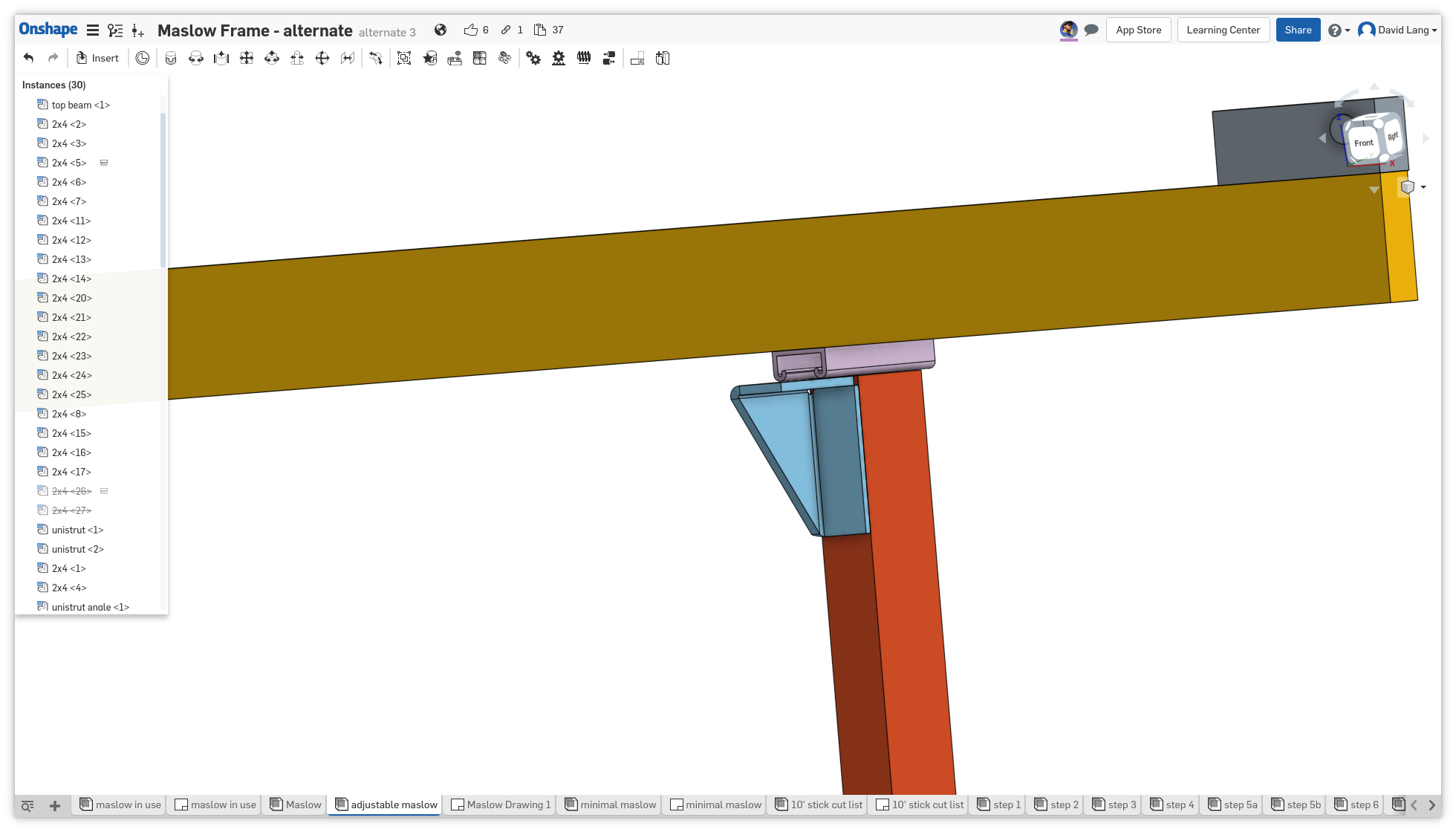
for attaching the top beam and adjusting it easily, these pictures from the 1000 post ‘new stock frame’ thread

This is rotated wierd (the red parts are the legs, the yellow part is the top beam, shown as a 2x4, but could easily be unistrut) The purple part is a piece of unistrut that can be moved by loosening the bolts to the angle bracket and then slid)

another view with a different bracket

with this sort of approach to make the top beam adjustable along the Z axis (and with a solid angle bracket to make sure it’s square to the legs), you can make it so that it’s very quick to adjust.

adjust the chain mounts to the sled so that when hanging from the chain it hangs straight or just slightly fop tipped towards the workpiece

mount a solid block to the leg (one on each side)

adjust the beam in or out until the chains are parallel to the frame with no workpiece (and no extra wasteboard)

mount a block to the movable unistrut that is now in solid contact with the fixed block

now you can quickly adjust the top beam position to the perfect position by taking a piece of material that matches your workpiece, and a piece of material that matches any wasteboard you are adding and pinching them between these two blocks. This will move the top beam out just the perfect amount to keep the chains parallel when cutting with that material.

For the sled attachment, the top mount kit has a pin that you put through the end of the chain into the metal arm (just a smidge smaller than the pins that ship with the stock kit)

it’s best to do this when you don’t have to support the weight of the sled, so you should have a hook/pin/bolt on the top beam at the center, and a hole/hook on the sled that lets you hang the sled from the center of the top beam to support it and keep it out of the way.

2 Likes

This frame is so close to exactly what I was thinking of doing in my garage! I am now considering tearing apart my freshly built new stock frame. I even have a chunk of unistrut! Then it would go flat against the wall next to my car and I could park inside for the winter!

2 Likes

I see there have been no postings for awhile here, but I just got my Maslow and am looking at doing a Unistrut frame as well.

In regards to the discussion for moving the motor mounts for aligning to the work peice, has anyone thought of 3d printing two laser pointer mounts for the chain attachment points on the sled, so that the lasers can point to the motors which will have a target mounted on them. To align the motor mounts you would adjust until the laser is lined up with the target?

Has there been any other progress on the unistrut builds?

3 Likes