Also, they say it’s only accurate within a couple of full steps, and switches
can be more accurate
- we don’t have switches
- since we are turning screws, that means that ‘a couple of full steps’ is a
very small distance.
David Lang
Also, they say it’s only accurate within a couple of full steps, and switches
can be more accurate
David Lang
I believe that I wired it up to be possible, but from reading online I found that most folks who tried it said it wasn’t reliable. I had a conversation with the guys over at Lumen PNP about it and they said that they found it worked about 95% of the time which was just enough to be a huge source of customer complaints and that they disabled it and went back to limit switches. ![]()
The tricky thing for us is that we don’t really care when the z-axis hits its limits, we care about when the router bit hits the wood, and I don’t think that the stepper drivers will be sensitive enough to detect that, so I think that integrating a z-axis probe option is going to be a lot more satisfying to use.
The good news is that FluidNC already supports a probe so it shouldn’t even require any firmware changes, just a change to the config file: Probe | Wiki.js
I’ve been tinkering the last few days on getting this working. I’ve had moderate success, but definitely not fully functional yet (most of my issues have been my own dumb fault like having the board upside down and attempting in vain for a day and a half to connect to the wrong GPIO pins). One thing I noticed though was that when I hit the “Probe” button in the Fluid NC tab to run the probe, it tries to run the gcode command “G38.6” (and some other configurable parameters). I believe it should be trying to execute “G38.2”. From a bit of research online, I believe that the higher decimals are for additional probes, but that a single Z probe should execute with the command 38.2. I’m not sure where to go to change that code.
As far as my tests so far (after using the correct GPIO pins), I started intermittently getting successful tests, but not consistent results yet. I noticed that if the probe wires get too close to the router power cord or the belt motors that the machine would begin rapidly reading successful probes. I’m assuming that’s due to some electromagnetic interference coming off of those parts. I’m wondering if a pulldown resistor or something is needed to prevent and/or reduce those false positives. Are there any internal pulldown resistors connected to Aux 1 or 2? Also, am I completely off base on using resistors here (I’m definitely not an electronics expert and still learning a lot of the basics, so I won’t take any offense if I am)?
EDIT: As noted in a post below, I added “pd” for “pulldown resistor” to the probe’s gpio config, and the false positives have gone away.
Bar wrote:
I believe that I wired it up to be possible, but from reading online I found that most folks who tried it said it wasn’t reliable. I had a conversation with the guys over at Lumen PNP about it and they said that they found it worked about 95% of the time which was just enough to be a huge source of customer complaints and that they disabled it and went back to limit switches.
The tricky thing for us is that we don’t really care when the z-axis hits its limits, we care about when the router bit hits the wood, and I don’t think that the stepper drivers will be sensitive enough to detect that, so I think that integrating a z-axis probe option is going to be a lot more satisfying to use.
No, it would not detect the bit hitting the wood, it would not be useful for
that.
What it could be useful for is two things
The question I would have about reliability is if the problem is false negatives
or false positives. If it occasionally misses that the steppers stall until it
tries a few steps, that doesn’t seem like that big a deal. But if it falsely
detects a stall when there isn’t one, that would be a big problem.
And with the EMI from a router, I fear the latter.
that said, it would be interesting to test the different modes and see if the
other modes are more reliable, stealthchop is intended to make the steppers
quieter, but it makes them less powerful.
David Lang
[EDIT: I’ve made a long post under the Wiki category walking through all the steps for making and configuring a z-probe (in detail).]
As an update, I just had a bit of time to play with things a bit more, and I’m pretty sure I have a working probe now.
Here is the code that I added/changed in the maslow.yaml file (the double-spacebar indentation on each line under “probe:” is required):
"
probe:
pin: gpio.48:high:pd
toolsetter_pin: NO_PIN
check_mode_start: true
hard_stop: false
"
Things to note:
There is already an entry in the yaml config file for a probe, but it is set to “NO_PIN” by default. You can replace that section of the config file with what I have above.
I tried adding “pd” for pulldown resistor to the GPIO pin setting in the maslow.yaml file, and it does seem to have eliminated the false positives from the power cord and motors.
The second wire connects to the “3v3” connection and does not connect to a ground terminal. I thought that the connections needed to be 1 wire to a GPIO auxiliary pin (I used gpio.48 aka Aux 1) and the second wire going to the ground terminal in order to complete a circuit. That did not work. After jumping various connections several times, I discovered that it works with 1 wire to the auxiliary pin and the second wire to the 3v3 pin. In terms of the 4 pin connector attached to the board, this equates to the second and third pins in the connector. I do not think that it matters which wire goes to which, as long as one wire goes to each. (See image.)
The rest of the set up is just a flat piece of metal under the sled. A wire connecting to the flat metal. An alligator clip with a small magnet (magnet isn’t necessary but can help keep things connected easier) connects to the router bit or collet. Those two wires then connect up to the Auxiliary 1 and 3v3 (doesn’t matter which or how you make the connection, as long as the wires get there, I just used some additional jst-hx connectors but whatever connects the wires and keeps them in place while probing should be perfectly fine). You want to have some sort of severable connection accessible near the board so that you can disconnect the probe and put it away while not in use without having to remove and replace the cap from the board each time.
The code to activate the probe is “G38.2 Z-[MT] F[FR] P[PO]”. MT = the max travel distance in mm that the machine will lower before stopping if a connection is not made. FR = the feed rate that the machine will lower in mm/minute; e.q., “F60” will lower at 1mm per second until the probe connects or it reaches the max travel distance. PO = probe offset, add a value here if you need to offset the thickness of the probe plate; if you use a piece of metal under the sled (as I described above) then this is set to “0” or simply left out altogether. An example gcode command is “G38.2 Z-50 F60”. This would have the machine lower at a rate of 1mm per second. If the machine does not make a connection after 50mm then the machine would stop and say the probe failed. If the machine makes a connection within 50mm then the machine will stop where it makes the connection and you can click “Define Z Home” to set the Z. After that, disconnect the probe and remove the plate.
You can unlock settings for the probe’s max travel, feed rate, and probe offset under “Preferences”; however, currently the button to start a probe is not working and the gcode command to start probing must be typed in manually. When clicking the button, it attempts to activate the command “G38.6” but the command should be “G38.2”.
This is the story of trying to do anything. Why is everything so hard the first time? ![]()
At least the joy of sharing is that once one of us figures something out everyone gets to benefit ![]()
I think that sounds like exactly what we probably need. Something like a 10k resistor would probably do it.
Nice!! Great solution!
I think the fundamental issue is that the stainless screws are moderately soft and the heads are small (shallow driver engagement) - definitely agree that star/Torx heads would be an improvement but, instead, I’d second @Beagle 's approach of swapping to socket head screws.
The handful of clearance issues with socket heads might be addressed with a low-profile option (such as what’s illustrated in the “Socket Head Profile” filter for McMaster-Carr’s options) - though I’m not sure how much that would erode the driver engagement benefit. Will try it out next weekend and update.
The other option would be to add a spacer under the idler gear, it only needs to be 2 mm max
Definitely move the controller board off the top of the router to the top of one of the sliding supports as that way the router can be any one of a number plus you can use the clones etc that have different cable positions
I would take this so far as to make the spools and the outer sleeve they rotate around be as wide as they can be while making it still fit inside the vertical posts and screws. This would maximize the amount of room for custom toolheads.
Carson Barry wrote:
I would take this so far as to make the spools and the outer sleeve they
rotate around be as wide as they can be while making it still fit inside the
vertical posts and screws. This would maximize the amount of room for custom
toolheads.
In general I agree with you, but the headache is that the belt then needs to
exit the arm. The belt comes off the spool at a tangent going to the encoder
wheels, so the distance out from the spool to the wheels results in a limit on
how narrow the arm can be at that point. The wider the arm is, the less it can
swing without hitting the verticals.
That said, we should play with things in CAD, if we can eliminate the idler and
make the distance from the spool to the encoders small, it may work (needs to
clear the gear and shaft of the motor)
David Lang
having done some playing around in CAD, I think this can be made to work.
using an idler for the belt such as WINSINN GT2 Idler Pulley 16 Teeth 3mm Bore 6mm Width Timing Pulley Wheel Aluminum for 3D Printer (Pack of 5Pcs): Amazon.com: Industrial & Scientific
This would let us expand the center opening to ~83mm, possibly 84mm, which would make it possible to use up to 80mm spindles and still have a cylinder around them to make them easier to remove
The resulting belt path and spool would look something like the orange lines in this image
David Lang wrote:
This would let us expand the center opening to ~83mm, possibly 84mm, which would make it possible to use up to 80mm spindles and still have a cylinder around them to make them easier to remove
20g metal is just under 1mm thick, 16g metal is just over 1.5mm thick
the next larger useful size is 3.5" (most full size routers, not including the
rigid router we used for the maslow 1) at 89mm, I think we would need to get to
95mm to handle the rigid router (3.75" IIRC)
It may be possible to make the flat side of the spool larger, so that it covers
the motor gear (eliminating the need for a separate belt guard.
increasing the spool diameter would allow for a couple extra feet of belt to
fit, but not many people have needed the extra length (which could mean getting
an extra mm or two on the inside)
also note, I didn’t check the new diameter for tooth count, so it may require
moving the motor a few mm in or out to get whole teeth on the spool
David Lang
I am in the vertical orientation with my machine and I have noticed that the lower z motor seems to have to work harder to move the axis up and down. Maybe its my imagination I’m not sure. What about swapping the rods with the z steppers? Have the steppers on the left and right and the guide rods top and bottom?
Also a thought about cooling with the dust collection- what about some kind of design that not only gets the machined material out of there but also helps suck the sled to the workpiece using the dust collection system?
Donavan Rekstis wrote:
I am in the vertical orientation with my machine and I have noticed that the lower z motor seems to have to work harder to move the axis up and down. Maybe its my imagination I’m not sure. What about swapping the rods with the z steppers? Have the steppers on the left and right and the guide rods top and bottom?
I was looking at the design in CAD recently and was thinking that having the
dust collection at the bottom is ideal for vertical mode (where the hose is
hanging off of it) but not for horizontal mode.
trying to put the dust collection around the rods is a nice idea in many ways,
but we then need to have the rod support tower go on top of the dust collector
plate (the clear cover), and if you had to remove the cover, you would need to
remove the tower (or have the cover slot around the tower and rod, still hard to
remove.
Also a thought about cooling with the dust collection- what about some kind of design that not only gets the machined material out of there but also helps suck the sled to the workpiece using the dust collection system?
sucking the sled against the workpiece also increases the friction between the
two, and is unpredictable (how much of the workpiece have you machined away in
such a way that air can get in through the slots)
David Lang
Should we be Z homing before every job? (Like a modern 3d printer does)
Dan wrote:
Should we be Z homing before every job? (Like a modern 3d printer does)
you need to set Z home any time you change the bit.
I don’t trust that the lead screws don’t turn when the machine is turned off, so
I would say you need to set Z stop every time you turn the machine on (I do tend
to be a bit on the paranoid side, not everyone does this)
If you have a job with a lot of Z moves, it isn’t a bad idea to st the Z stop
and Z home in case the steppers missed a step at some point in the process.
David Lang
As a quick note, if you’ve already inserted a bit, you can still re-set your Z stop, you just need enough clearance under the bit for the stepper motors to click (that amount of clearance will depend on your bit). I always think about re-setting the Z stop after I’ve inserted a bit and I don’t want to remove it to set the Z stop. It took me longer than I’d like to admit before I realized that I could just prop it up so the bit won’t hit a surface, lower the Z all the way, set the Z stop, then raise the Z again until the bit has a safe clearance.
Just to be clear, there are 2 Z settings. 1) The Z stop. 2) The Z home.
Z Stop: Z stop tells the machine when the z-axis stepper motors are at their lowest points. As @dlang says, you do not need to re-set your Z stop every time you change your bit. I think most people probably don’t re-set their Z stop all that often, but that’s up to you. You can do like @dlang and set it every time you turn the machine off and on again. I probably do it once every couple weeks.
Z Home: Z home tells the machine where the top of the material is located in relation to the bit. Effectively, this is the point that the router bit first touches your material and is used by the machine as the reference point for the depth of all the cuts you are about to make. This should be set every time you change your bit. I would also re-set it in the event that your are cutting and the cutting fails for some reason (sometimes after it fails, it will get confused on where the bit was when it failed, so you’ll need to re-set the Z home).
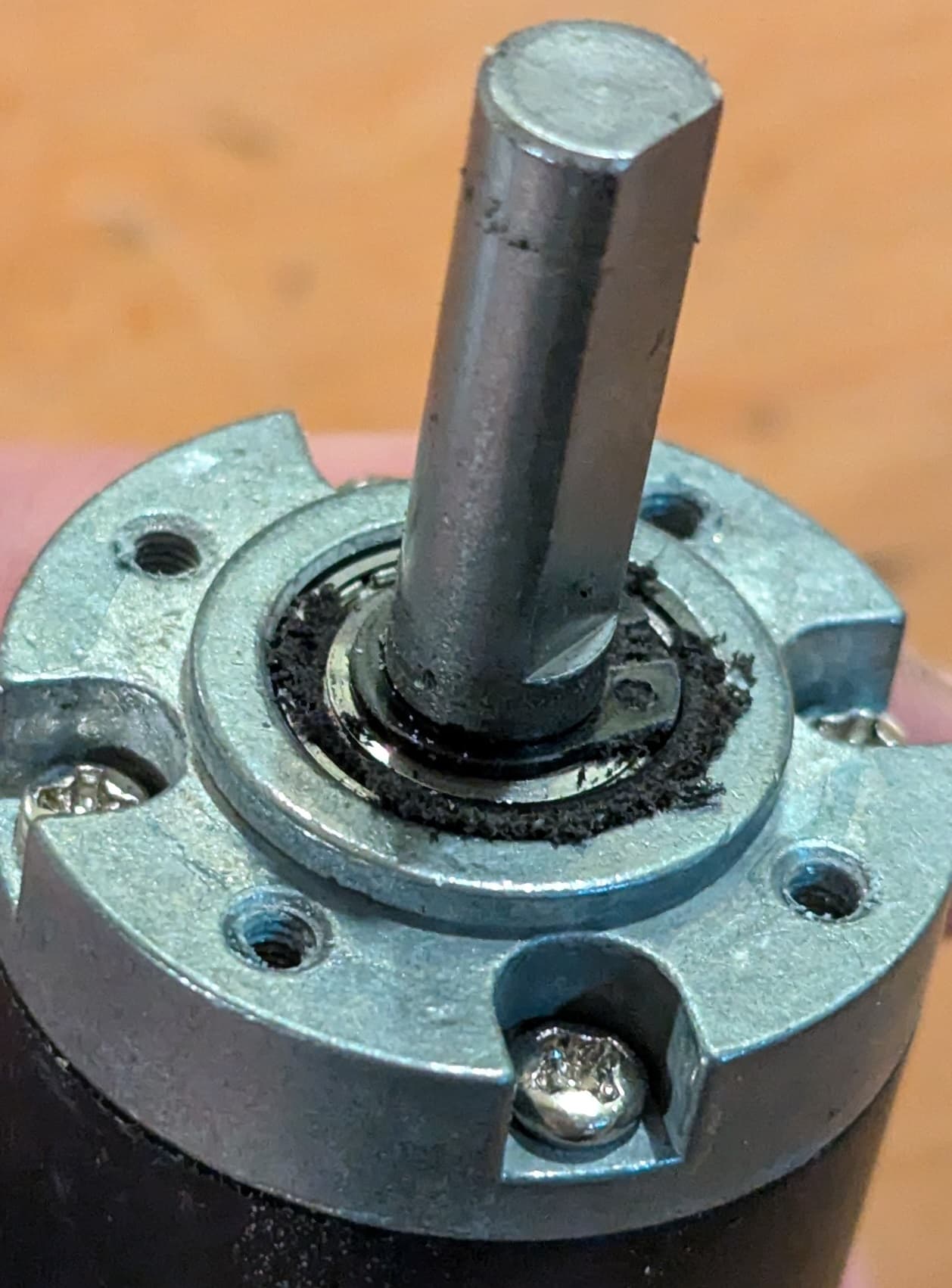
I think the arm frame needs a shallow pocket around the motor/gearbox shaft (on the outside face). I opened-up all my arms this weekend (anticipating arrival of the new JST XH encoder boards/controller - also trying to understand more about non-uniform current demand across the arms) and discovered that a ring of the plastic had been worn away. The plastic debris has been trapped around the shaft and ground to a fine dust/paste consistency - no sign of harm, but it can’t be good to have that circulating around the gearbox’s output bearing.
It looks like there’s a retaining ring on the shaft that extends slightly beyond the face of the gearbox - I suspect that’s what’s causing the wear.
Here’s a new arm frame for reference
Here’s a worn arm frame
And here’s the debris