I posted the more efficient spool earlier, that lets you have the same size spool holding a little more belt. combined with the option to have the flat surface of the spool overlap the idler gear a little bit (it looks like 131mm diameter would work) gives us just a little more room in the center.
One thing that could be done with this is to modify the arm to have bearings in it rather than plastic on plastic. I found three bearings on Amazon that may be useful that all ride on a 3mm shaft (so could potentially just sit on the bolts)
type 683 3mm id x 7mm od x 3mm thick
type 693 3mm id x 8mm od x 4mm thick
type 623 3mm id x 10mm od x 4mm thick
currently the core of the arm is 6mm thick, with the bolt holes offset away from the spindle. It should be possible to use the 7mm or 8mm bearings to make an arm that has two sets of bearings, one offset towards the spool, the other offset against the spindle.
idler and motor in the same position, 82 tooth spool (matching the original) but with room for 4500mm of belt on the spool (what you ship with, but by extending the flat area of the spool to overlap the idler, it fits better)
ofsetting the bearings 15mm from each other results in:
with 7mm bearings, this gives a 73.5mm spindle
with 8mm bearings, this gives a 71.5m spindle
with 10mm bearings, this gives a 67.5mm spindle
If these parts were not made from plastic, I would use half as many bearings (3 per surface instead of 6) but since I expect the plastic to flex I went with 6
Here is a twist on the maslow idea. This uses ‘standard’ leadscrew steppers (not low profile and using a standard leadscrew length rather than a special order) and gives about 4in (just under 100mm) of Z travel, which would make bit changes much easier. The clamps also cannot run off the top and we can put homing sensors/stops at the top to be able to home away from the workpiece.
It has slightly better side/top angles than stock (instead of about 40 degrees with the stock maslow, this gets about 30 degrees for arms where there isn’t a leadscrew and about 35 degrees where there is, unless we make the ears to the screw leads thinner)
by trimming off the ears and using the lead screws instead of the guide rods, we eliminate the angle problem in the corners.
This gives us full green coverage on a 4x8 sheet of plywood on a 10’x7’2" (3048x2184mm) frame
The vertical braces have right angle braces, so would be far more rigid than the current towers. those braces are about 4" wide (and the arms will hit the clamps before the belts hit the braces) which gives room to mount power supplies, electronics, etc.
I don’t know if the 8mm lead screws would be weak enough to be a problem. The force is applied to the router so they don’t have to handle cutting forces, just dragging the sled along. but if the arms end up riding on a cylinder attached to the base, all they need to do is to move the spindle up and down with the cylinder handling all the forces (requires a code change to support)
I haven’t worked on dust collection, if you do use a rigid cylinder, could you suck up past the spindle (cooling the spindle in the process)???
This looks excellent!
I think it might be a good idea to extend the gray motormount piece so that they also connect to the yellow straight pieces for a healthy dose of extra rigidity, need to carve a slight recession in the yellow pieces so it can simply be glued together using a couple of clamps. The gray motormounts could also have some slight recessions to help get a firm and properly set mounting position, with the use of ply and wood glue I do not think screws are needed at all.
Thinking.
Would be much more resilient against certain forces if there was at least one guide rod per lead screw.
You all know that guy that needs a bit of extra consideration from time to time, his name is Case, Justin Case.
Thinking.
Would be much more resilient against certain forces if there was at least one guide rod per lead screw.
how much force is involved and are the 8mm lead screws rigid enough? adding 6mm
guide rods would not be a significant win, how large would you want to add?
aligning the lead screws and the guide rods adds a thing that can be done wrong,
so if we can get away without it, that is a win.
The stepper mounds do have a recess to notch into the towers. I designed both square and diamond mounts (initially looking for the motors to interfere with the steppers less, but then decided that there was enough height to just have the Z axis stop so the motors clear the mounts). With the square mounts, you could mount the motors below the mount, leaving less stuff to catch at the top (at the cost of the towers being taller) you could also put bearings on the towers just above the top clamps to add rigidity to the leadscrews (reducing their unsupported length from 300mm to 200mm)
There is a lot of room to tinker with dimensions, use a dado in the yellow pieces, etc. Those tower pieces were shown as straight just as that was the simplest to model.
But the best way to make improve the rigidity is to make a cylinder that is solidly mounted to the sled and ahve the arms ride on that rather than going up and down with the spindle
It looks really good, and looking at it more thoroughly I see what you are saying about the rods. Still think it would be nice to have that top motormount connected to both pieces, it should be little to no cost for a fair bit of extra torsional stiffness.
Im working on bearings version of my maslow. I already have modified arms which house a bigger router ID 90mm. Since I am now opting for a spindle instead of the router it gives me room to add bearings (90x70x10mm) (red) to the spindle mount (70x55). In between the bearings i will use spacers and bearing mounts so that each arm can be cleared from the other arms.
Hi, I was thinking along the same lines, but wouldn’t it be better use of those large bearings to use them for the spools instead of the arms? Together with the bearings for the idler gear it will be a low friction geartrain
Yea, the spools will have more wear indeed. I can however still add small bearings to the upper section of the spool arm in the same way as Dlangs drawing. His method seems to be more cost effective. The one benefit this has IMO is that I can more easily create clearance between the arms. Maybe there is also an advantage that the arm bearings are different of the spool bearings in this case but probably not.
Hey @bar I was assembling my upgrade kit and an idea occurred to me.
In your prototype phase did you consider making the vertical support, z axis, vertical rails to be on the inside of the belt spools? Sort of like a beefed up router sleeve inside the spools. I’d imagine the spools would have to be increased in diameters to accommodate . but we potentially reduce the interference from the support arms. And possibly more belt capacity.
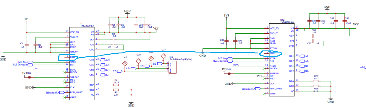
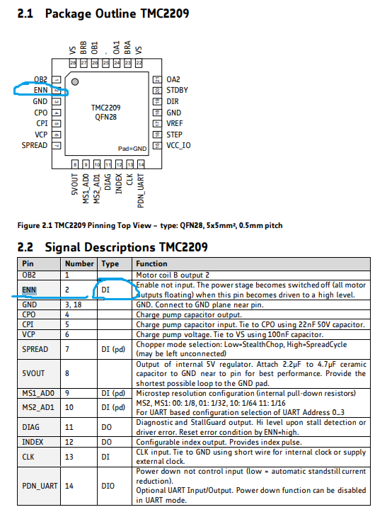
Are the TMC2209 ENN Pins unconnected and floating? If so, is that intentional because enable/disable happens via UART?
Am wondering if this could be causing some boards to have one or both Z stepper motors unexpectedly/randomly not work.
Am wondering if people with “bad boards” (that they would normally just trash) and unreliable Z axis behavior, but also have brilliant eyesight, dexterity and a fine tipped soldering iron… might see better behavior if they solder blob the TMC2209 ENN and GND pins, or jumper to one of the Aux GPIO pins that can be configured in firmware to toggle ENN?
Have been looking at https://github.com/MaslowCNC/Boards, asking because I’m used to seeing ENN pin driven by a GPIO, or, tied to GND to keep drivers always enabled. Sorry if this is a silly question, am relatively new to driving Stepper motors directly, related chat. Am learning by digging around projects I like, and was curious about this observation.
4.0 and 4.1 schematics show TMC2209 pin 2 floating…
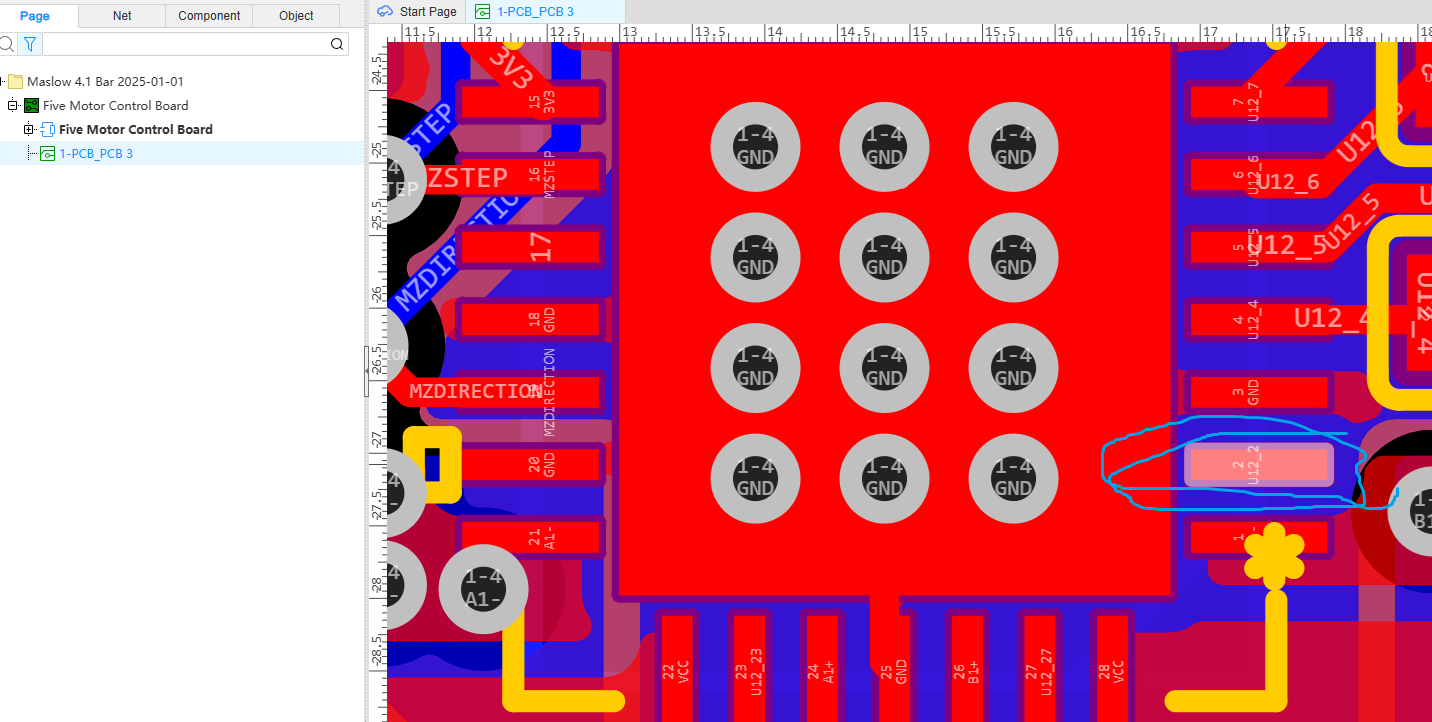
I haven’t physically inspected a board (e.g. test resistance between Pin 2 ENN and Pin 3 GND), partly because of eyesight and dexterity needed to precisely probe continuity of those TMC2209 pins.
I haven’t closely inspected the firmware to see if/which GPIO Pin toggles ENN pin. Maybe the schematic and PCB design snapshots from GitHub that I’m looking at are outdated?
Neat! Curious if anyone explored this, maybe for a pendant with physical buttons/rotary?
I actually just ran through that board too and noticed the same thing. I just put out version 1.12 which ties those to ground and adds a diode so that 24 volt power is not needed when flashing them. That’s mostly an improvement for the factory to save time, but it will be a nice update generally.
Neat, thanks for sharing, am checking out, mainly to learn…
Could the floating ENN pin be contributing to some of the Z axis issues some Makers are encountering (that are not because of mechanical binding) where one or both steppers sometime do not work? Would the very careful blob soldering of Pins 2 and 3 GND help fix if bold, eagle eyed, surgically hand gifted people encounter this issue?
Import isn’t working for me, I tried EasyEDA Std Web, Std Client (latest), Pro Web, Pro Client (latest). Tried earlier versions even… Unzipped file contents hint that EasyEDA Std Web was used based on “EasyEDA v6.5.50, 2025-06-23 19:09:50”. Dug around EasyEDA forum and reached out to their support.
Low priority, am not blocked, I’m switching to doing something else now, but sharing incase others are seeing this too?