Where I live the only alternative router is the Dewalt 26200, unfortunately the pcb mount does not fit and the vertical facing power cord also gets in the way so I have designed a 2 part attachment method which clicks onto the side vent of the router top and slightly offsets the power cord so it no longer gets in the way. I would love to attach the files but unfortunately the system here says new users may not upload files… Is there a way around this?
Update: I can now upload so here it is. Before attaching the Holder Mount to the top of the router lightly tap in left over nuts
Thank you very much for this. I printed it in ABS. I found I had to redesign the clip portion - the 1.5 mm overhang put too much strain on the clips and they broke (even after I tried again and upped the infill to 50%). Maybe PLA would have been more flexible.
Having reassembled the router, I find that the rotation of the control unit anticlockwise from the top combined with raising it to accommodate the screws holding the two halves together makes the cables to the lower motors & sensors too short (if the motors are assembled according to Assembling the router 4.1 — Maslow ) and the arms are rotated clockwise (dictated by the position and frame). This is not an insurmountable problem if one changes the order and programmed setup heights of the motor/spool units, but that will break my calibration etc. Or I could try to find or make longer cables.
I will have a go myself at a UK DW26200 mount and if I think I have something worthwhile I will share it.
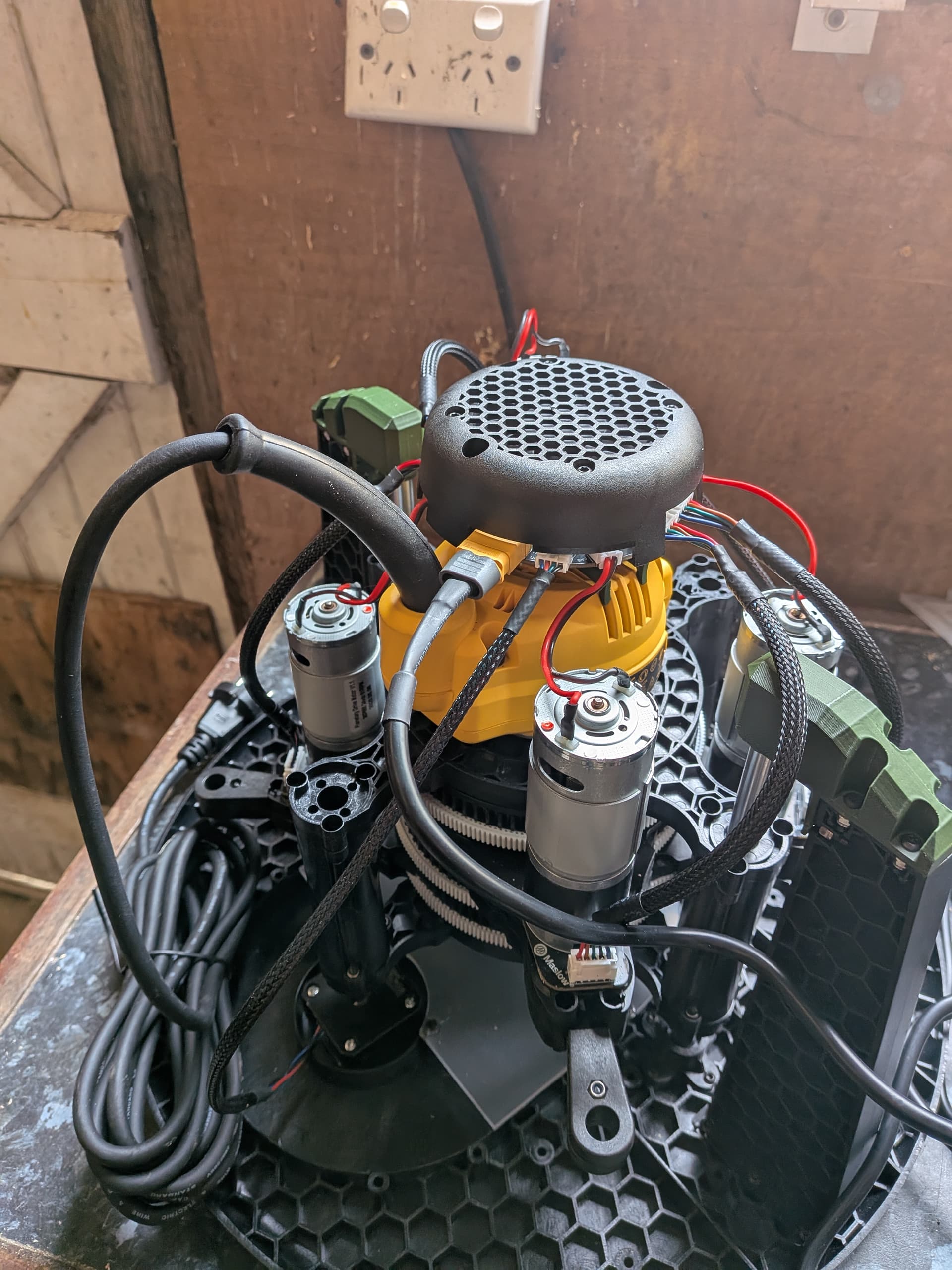
This is with my attempt at a one piece mounting clip on a UK spec Dewalt 26200. It is significantly lower than the one oddbyte was kind enough to share, and rotates the unit clockwise rather than anti-clockwise viewed from above. With this version the lowest motor has full travel without stretching or disconnecting the sensor cable. Unlike oddbyte’s version, it needs quite a lot of support when printing. I printed it with the top side on the hotplate.
Hi Anthony_Huggett, that’s strange I haven’t had any issues with the cables. Looking at the image you attached it seems to be a fair bit higher than mine. When you modified it did you add some height? Also I printed mine in petg. Cheers
I believe my height on the two piece is the same as yours - the router clip body is the same thickness to 0.1 mm and I used the same top part. (I would have modified yours but couldn’t figure out how to make Fusion 360 do that, so I copied it with a Vernier gauge for the key measurements). Maybe PETG or PLA would be better & more flexible.
Of necessity the 2 piece design accommodates a screw vertically between the router and controller, which probably makes it 15mm rather than 5mm. The sensor cable stretching/disconnecting would likely only become an issue at the bottom right corner of the full work area.