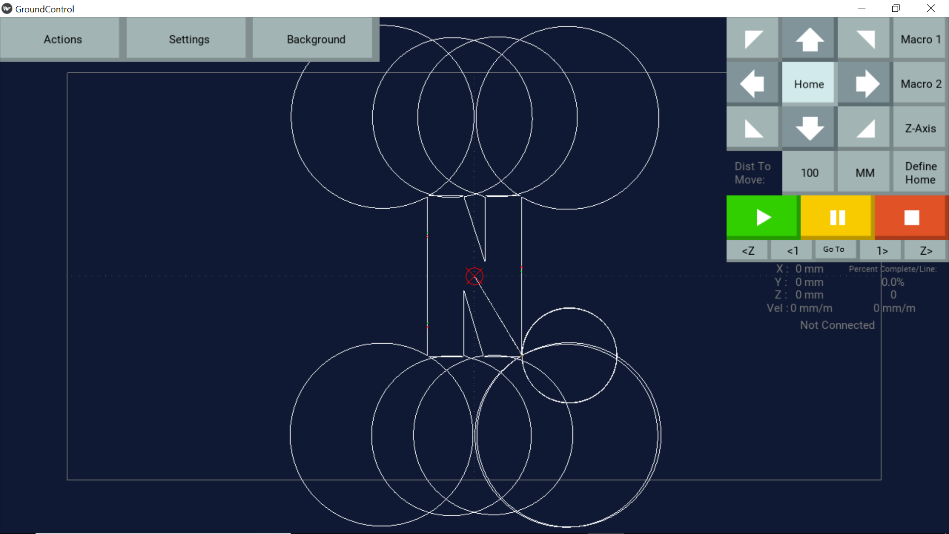
Anyone got any idea what I am doing wrong here please? I have only just finished calibration on the Maslow and trying to cut a few things out this week a a tester. The letter with 4 passes works fine in Fusion 360 but looks bizarre in Ground Control, I guess I am missing some setting somewhere but it is not obvious to me what it is.
Close up of the corner

What is the version number of Ground Control you are using? We had an issue like this in the past which was fixed, maybe this is related.
Will you post a copy of the gcode file?

I did a basic rectangle and the same thing happens, thought that would make it easier to analyse the GCODE.
Ground Control version is 1.26
I should mention that I can cut the sample GCODES that came with Ground Control with no difficulty.
: (PGM, NAME=“1001”)
; T1 D=6.35 CR=0 - ZMIN=-6.2 - FLAT END MILL
: G90 G40 G94
G17
G71
M26
; 2D CONTOUR1
M9
M26
:T1 M6
M26
S12000 M3
H0
G0 X39.848 Y22.805
Z15
Z5
G1 Z1 F167
Z-5.565
G19 G2 Y22.17 Z-6.2 J22.17 K-5.565
G1 Y21.535 F500
G17 G2 X39.213 Y20.9 I39.213 J21.535
G1 X-40.195
G3 X-43.37 Y17.725 I-40.195 J17.725
G1 Y-17.725
G3 X-40.195 Y-20.9 I-40.195 J-17.725
G1 X40.195
G3 X43.37 Y-17.725 I40.195 J-17.725
G1 Y17.725
G3 X40.195 Y20.9 I40.195 J17.725
G1 X39.213
G2 X38.578 Y21.535 I39.213 J21.535
G1 Y22.17
G19 G3 Y22.805 Z-5.565 J22.17 K-5.565
G0 Z15
G17
M26
G0 X0 Y0
M30
M2
What is the post-processor you are using in F360?
Did you try this one? fusion360-post-processor-for-maslow
bCNC and Camotics also display a strange views and the small circles are vertical.


This is in the CAD/CAM workflow. Try the Maslow post-processor or alternative Grbl, Linux-CNC, Mach3.
Kind regards, Gero
Edit: G19 in the code!
G17 is XY plane, G18 is XZ plane and G19 is YZ
Edit2:
I took out the circles and some strange zig-zag, plus the G19 from a different plane, corrected 2 wrong x-coordinates and removed all ->‘:’<-.
This is what a simple rectangle looks like:

1 Like
it might be best if you share the fusion file for that rectangle, that way someone can look at it and see where the problem is. I’m willing to bet something isn’t set up quite right in the cam settings…
you keep saying you are using a simple rectangle, but based on the g-code, it’s doing a rectangle with rounded corners (and generating the wrong g3 lines for those corners)
they look like a reasonable radius, but with the center in the wrong direction.
2 Likes
OK, what dlang said there made me go back through some autodesk forums and I finally figured out that I was being a bit of an eegit and hadn’t noticed that it was set to ‘rollover corners’ in the passes section instead of ‘keep corners sharp’.
Thanks for the replies, onwards and upwards, will post pics of project when it is done.
1 Like