In response to that post, @BradM created a nice tool to calibrate the Malsow 12 O’Clock chain positions.
I designed a CNC version of it. Here you’ll find a description of how I made that with FreeCAD.

If you would like to follow-up, you should get the free open source FreeCAD tool version 0.18 or later. (As of january 2019, do not the CONDA flavor as some bug disables tag generation).
Then download the 12OClockLevel FreeCAD project distributed here under a free and open source GPLV3 licence.
Step 1
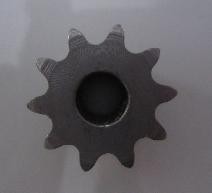
Took a contrasting picture of the gearbox sprocket, using my camera with some close-up ( macro) focus capability.
Step2
Imported into free and open source Inkscape. Used menu “Path/Trace Bitmap” to convert the bitmap into a vector shape. Then ungroup the set of shapes, keep a good one showing at least part of the sprocket profile. Edited the shape (cut nodes to isolate one good teeth, Path/simplify to reduce number of nodes for same shape, and duplicate / rotate 10 times at 36 degree) to rebuild a full sprocket profile shape (right click and download the shape to get the actual SVG shape file).

Note: use color fill, no contour on the inkscape shapes. This makes FreeCAD importation more accurate.
Step 3
Tried to make a shape that can be CNC with a 3.17mm (1/8th inch) router bit… But should have kept it like that.
Step 4
Setup the inkscape file properties to use mm units, scale the sprocket shape to be like the real one. Having a caliper here is quite necessary.
Step 5
Added a rectangle above the sprocket shape to position the level vial cutout. Now, FreeCAD will let you tune the shape later if you want. But to get a good fit later: a caliper.
Step 6
Combined a copy of the vial level cutout and sprocket shapes (path/combine) and used the menu “path/dynamic offset” to create shape that can be swelled using a handle. Swelled until made them touch to overlap. Used path/union to create a single closed shape. Then “path/brake apart” to get rid of all little artefacts like holes. Selected the swelled contour only. Cleaned-up nodes to give the contour the desired V shape surrounding nicely the sprocket and level vial.
Step 7
Added a circle in the sprocket shape center, then align everything using menu object/align and distribute. Make sure each shape is closed (has a fill color).
Step 8
Saved SVG file as a plain .svg file – NOT inkscape .svg file
Here is a file showing the result (again the sprocket shape was overkill here)

Step 9
Opened FreeCAD, created new project, open part workbench and created a new part.
Step 10
File/import selected .svg file and chose import as geometry when prompted. At that point got a set of shapes. Not yet sketches.
Step 11
Opened the draft workbench. For each shape, menu “draft/Draft to Sketch” once with each shape selected to create a set of equivalent sketches. From that point only use the sketches.
Step 12
Used Sketcher workbench to edit sketches to clean them up: (I did not fully constrain the sketches. I kept closed loop sketches)
- Replaced the circle with a real circle: The inkscape import created a B spline and that is not supported by all path generation tools. Especially not the Helix which I wanted to use.
- replaced the level vial slot with a real rectangle
Actually, B-Splines are complicated shapes and the Path Workbench will slow down if you get too much of those. That is why I prefer to use sketches with FreeCAD shapes instead of inkscape. But here the sprocket was definitely worth the svg import!
Step 13
Used part work bench to extrude the contour sketch, then the part design workbench to pocket holes partly or completely using other sketches.
Step 14
When trying to make CNC paths, found out that the sprocket tips needed to be cleared, but a 3.17 mm bit can’t go in. Added a set of 10 circles pocket with polar pattern to drill the tip of the sprocket teeth.
Step 15
Once the part was defined, opened the Path workbench to create a path CNC job, operations and simulate stock machining, then exported GCode.
I invite you to inspect how the 12OClockLevel FreeCAD project is built.

To learn more about Path workbench, I strongly recommend Sliptonic’s youtube tutorials. I don’t get benefits for that recommendation. But I got all my FreeCAD and Path workbench starter skills with it 
Step 16
Inspected GCode with CAMotics and looked good. But later found that G81 (drilling) is not suported. And had to replace the GCode lines with equivalent sequence:
G81 X16.2196 Y16.1716 Z-9.0000 F300.00 R10.0000
becomes
G0 Z1.0000
G0 X16.2196 Y16.1716
G1 Z-9.0000 F300.00
G0 Z1.0000
Where the R10 retract is simplified to pull the drill up to 1mm instead given the MaslowCNC nature.
Here is a reference for GCODE commands at LinuxCNC
Step 17
Then I had to tune the fit. Again with a caliper I could see that my cutter was cutting 0.15mm too close when profiling. So I mofified my tool in FreeCAD to set it 0.3 mm diameter bigger (3.5mm) and that actually made the path get further away from the profile faces. My cuts were then snugly tight.
Note that to effectively modify a tool in a CNC job, you have to double click on the tool controler of the CNC job, then look at the end of the settings panel to see the TOOL tab, expand it and change the tool diameter there. If you change it in the tools manager, the change will have no effect unless you delete and recreate a new tool controler for the job.
And that is it.
Let me know if you try FreeCAD projects on MaslowCNC!


