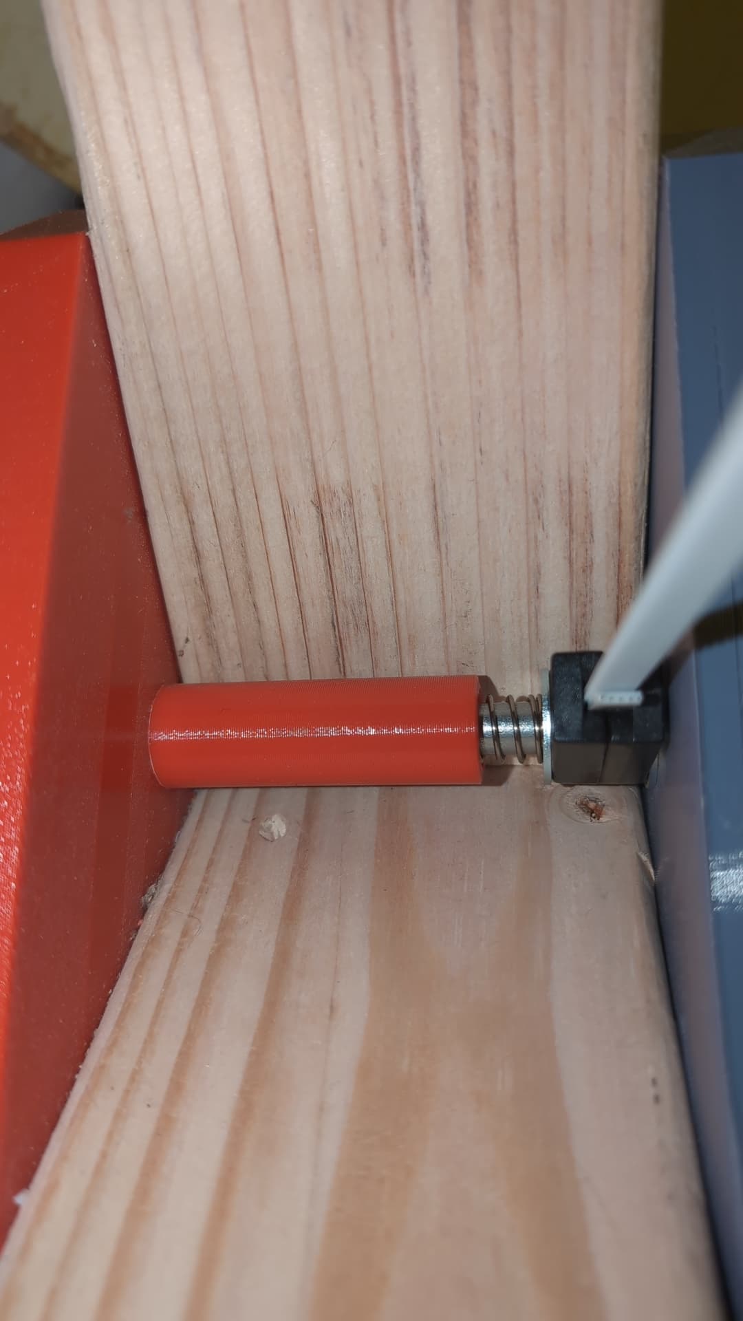
When calibrating, I noticed the belt ends were sliding up and down the axle on the Z plane. They need a way to stay in a stable position. I quickly designed a spacer with a spring to keep the belt end pressed to the top. Fitness went from .35 to .71 without other changes.
On a vertical frame, it is unsafe and barely possible for a single person to mount without some sort of brace holding the router in the middle. A D ring and bungee cord fixes that.
Haha, oh no, it didn’t dawn on me people are mounting the belt ends on top of the top frame plate. I think I could do that but I’m surprised it doesn’t loosen!
When calibrating, I noticed the belt ends were sliding up and down the axle on
the Z plane. They need a way to stay in a stable position. I quickly
designed a spacer with a spring to keep the belt end pressed to the top.
a spring still lets the anchors move up and down, it just takes more force. you
should put a solid something there to keep them from going up and down at all.
That was my original thought but
A) Wood dimensions aren’t perfect, and my 3d printed corner brace. It’s sub millimeter accuracy but what might fight tight on one side won’t fit at all on the other without a hammer. A cut spacer would result in movement on the Z axis because of imperfect 3d printing and wood. The spring I knew would work for any corner that isn’t exactly the same width. They’re all within a millimeter but eh.
B) Only upwards forces are placed by the device. The only downward force is gravity on the belt end when there is no tension on the line. As long as the spring fully resists gravity of the belt + end when it is slack, there is no movement! The spring is pushing up, not down.
C) A spring is universal for anyone else with the same problem
D) Maybe most people are mounting to the top of the frame above the corner bracket. It didn’t dawn on me until I stumbled across a random assembly photo, I didn’t see an explicit callout in the user manual. That’s my misunderstanding. A spring would not be needed there, but then a cotter pin is also better than a bolt.
E) I did manage to get a very good calibration fitness with it, and calibration finished quickly whereas it failed twice without
F) It’s not unheard of, many CNC machines use eccentric nuts or springs or other things for alignment, when the spring or friction will fully resist forces at hand
I’m going to have it draw some shapes with a pencil soon, and if it’s off at all I’ll move to mounting the Z on top of the corner brackets.
There might be an advantage to my misunderstanding - there’s only significant lateral forces on the bolt, so it can actually be not tightened down at all. Any extra upwards force is going right into the frame through the corner bracket instead of pulling on the bolt and on any slop in the cotter pin.
As a new owner with a vertical frame, the bungee solution has immediately changed how I feel about troubleshooting the extend retract cycle. It was sitting right there as a solution, so thank you for pointing it out. I have looped my bungee through the vertical support and have just hooked to the top of the spoil board.
I have two additional mods I’ve made as Projects on the Way to the Project™.
Round Over Gussets
The first was because I noticed that with some belt lengths the bottom belts would get caught on the gussets along the bottom of the frame. I removed the lower gussets and hit the top perimeter and lower corners with a 3/8” round over bit. I had a second trim router, but this could easily be done with the router to be installed into the Maslow prior to machine assembly.
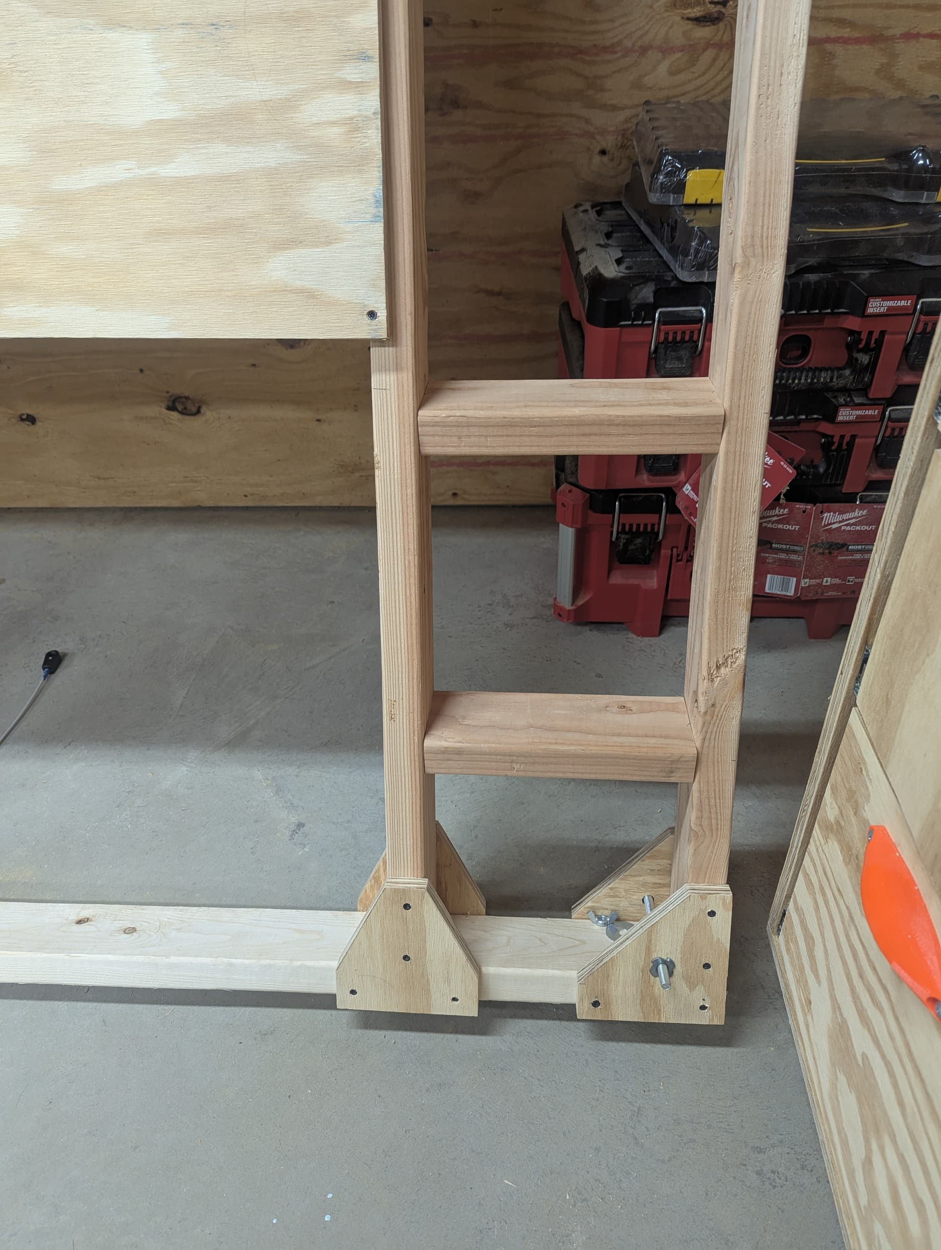
As I’ve repeatedly performed the retract all/extend all dance I grew tired of moving my step ladder from its storage position to each side of the frame and back to storage. I’ve cut two 2x4 blocks for each side and mounted them at 12 and 24” like my ladder’s rungs using 3 1/2” construction screws. A couple of shims took care of any shifting of the frame as I stepped up.