Hi all,
I finally performed my first cut other than the final sledge.
I modeled a shape in fusion 360, did the cam in fusion and started the job.
While cutting the first pass the Arduino power supply died (maker made).
I ordered a power supply transformer on Amazon, since last shipping from maker made took 5 weeks. Same specs: 12v 5a center positive.
I restarted the job and finished the cut.
Now, the cut line looks really bad. Wawy, irregular. Especially in the horizontal lines.
Could this be an issue due to the new power supply? Position of the cut (top of the working space)? Calibration? Or maybe just chains tensioning/sledge dragging?
I also noticed that the cut part is bigger than the model in Fusion. About 4mm.
In the geometry tab of fusion nothing was changed from default other than selecting the path and checking that it is an outside cut.
Picture doesn’t show for me either. 6.35mm deep passes could be your issue. Rule of thumb is half the diameter per pass so try 3mm and see how it responds.
I did sand the inside of the ring, sanded the bottom of the sled and routed the outline as suggested somewhere. I will sand more. Also I didn’t have any bungee cord on the router.
I will try to go slower at 3mm at max rpm for the ridgid router and report.
As for the cut being bigger than the model, I tried a quick test and a 100mm square had 2 inches added both x and y. One of them was smaller, I forgot which one, so it doesn’t cut square right now.
I processed it with the generic GRBL. I now installed the Maslow one and will try to cut the square again.
Maybe I should also recalibrate? I was waiting to do that for after I finish to put together the steel frame and the Meticulous z-axis modification.
I did sand the inside of the ring, sanded the bottom of the sled and routed the outline as suggested somewhere. I will sand more. Also I didn’t have any bungee cord on the router.
I will try to go slower at 3mm at max rpm for the ridgid router and report.
you probably want to run at about your slowest speed, running to fast will heat
up the bit and burn the wood.
As for the cut being bigger than the model, I tried a quick test and a 100mm square had 2 inches added both x and y. One of them was smaller, I forgot which one, so it doesn’t cut square right now.
I processed it with the generic GRBL. I now installed the Maslow one and will try to cut the square again.
Maybe I should also recalibrate? I was waiting to do that for after I finish to put together the steel frame and the Meticulous z-axis modification.
if you are off on your dimensions, that’s a calibration issue, not a gcode
post-processor issue.
I tried a slower cut. Went down only 3mm. Rubber bands on the router. I fixed some issues on the g-code generation from Fusion 360. I looks better already.
Now, as for the dimensions issue, you guys suggest calibration and it makes sense.
As for re-calibration, should I run it from scratch? Like… remove the sled, chains and redo the whole thing, maybe even cutting a second final sledge?
Thanks for your help
As long as the bit is centered in the ring, there’s no need to re-cut the sled.
but I would go back through everything. Also manually measure the motor
distance, the chain is a little longer in practice than the specs say, and that
can throw off the automatic measurement.
“No judgement” is really appropriate in this case. Gero you are right.
I bought a flat end mill a few months ago for a project, Used it and threw it back into the router bits storage.
Then a few weeks ago I bought an end mill ad suggested in the forums, 1/4 diameter.
I threw that in the router bits storage.
When I set up the Maslow I was so excited that I forgot that I had two flat end mills. Murphy’s law had me picking up the wrong one, which was smaller in diameter. I forgot the size in imperial, but it is about 5mm. That explain why I was getting a 102 mm cut instead of 100 mm.
I swapped the bit, reduced the travel speed, reduced the spindle speed, put two rubber bands on top of the router, learned how to manage depths in Fusion 360 and I got a nice cut with perfect tabs and all.
I measured the sled and it is centered, as far as I can tell.
Now, lines are straight, sizes are about right. Slightly on a taper (the improved z-axis setup should fix that, or maybe just working with the balance of the sled). I still have about 0.6 mm of difference between horizontal and vertical cuts (vertical being shorter) but I feel that a more precise re-calibration will fix this as well. Diagonals on this square cut are spot on.
I re-calibrated, this time with the right bit size. I 3d printed a tool to attach to the motors to tell the exact 90 degrees (even added a spirit level to it).
When I cut the test cuts, 1-2 and 3-4 were off about 4mm. Is this normal?
I then cut the same 100mm test square. Now it is even worst than it was before.
Where is the most important part of the calibration? There is a way to manually adjust it?
The motor distance is mostly ‘off’ from what i measure better by hand. The rotation radius should be fixed value if you have 1 of the triangular kits. Y-offset is worth a check also.
If you feel like the calibration is too far off with it’s numbers, you can adjust them to what you measured.
Edit the .ini with GC closed. Use at own risk
I will try.
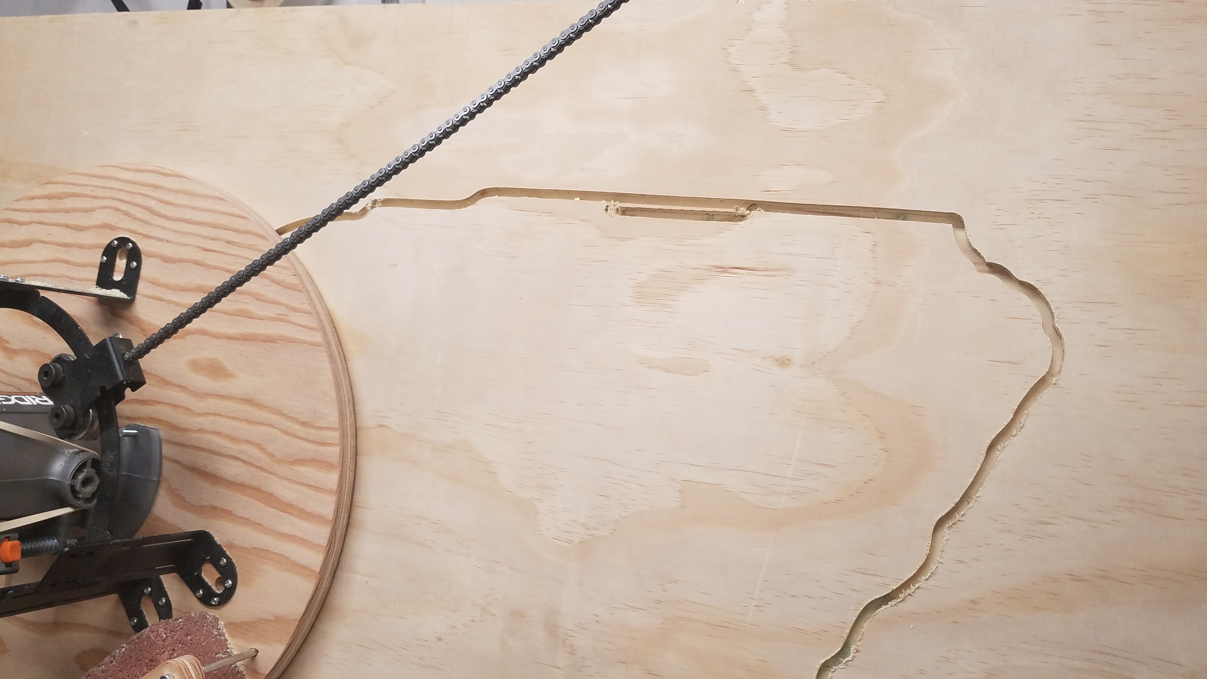
To enjoy a little this machine, I gave the calibration problem a break. Then I stumbled into another issue. I was cutting an outline of Oregon on ply.
Speed of cut set at 1000mm/min
Passes 3mm
1/4" flat end mill, up spiral.
Speed dial or the Ridgid router set at 19000
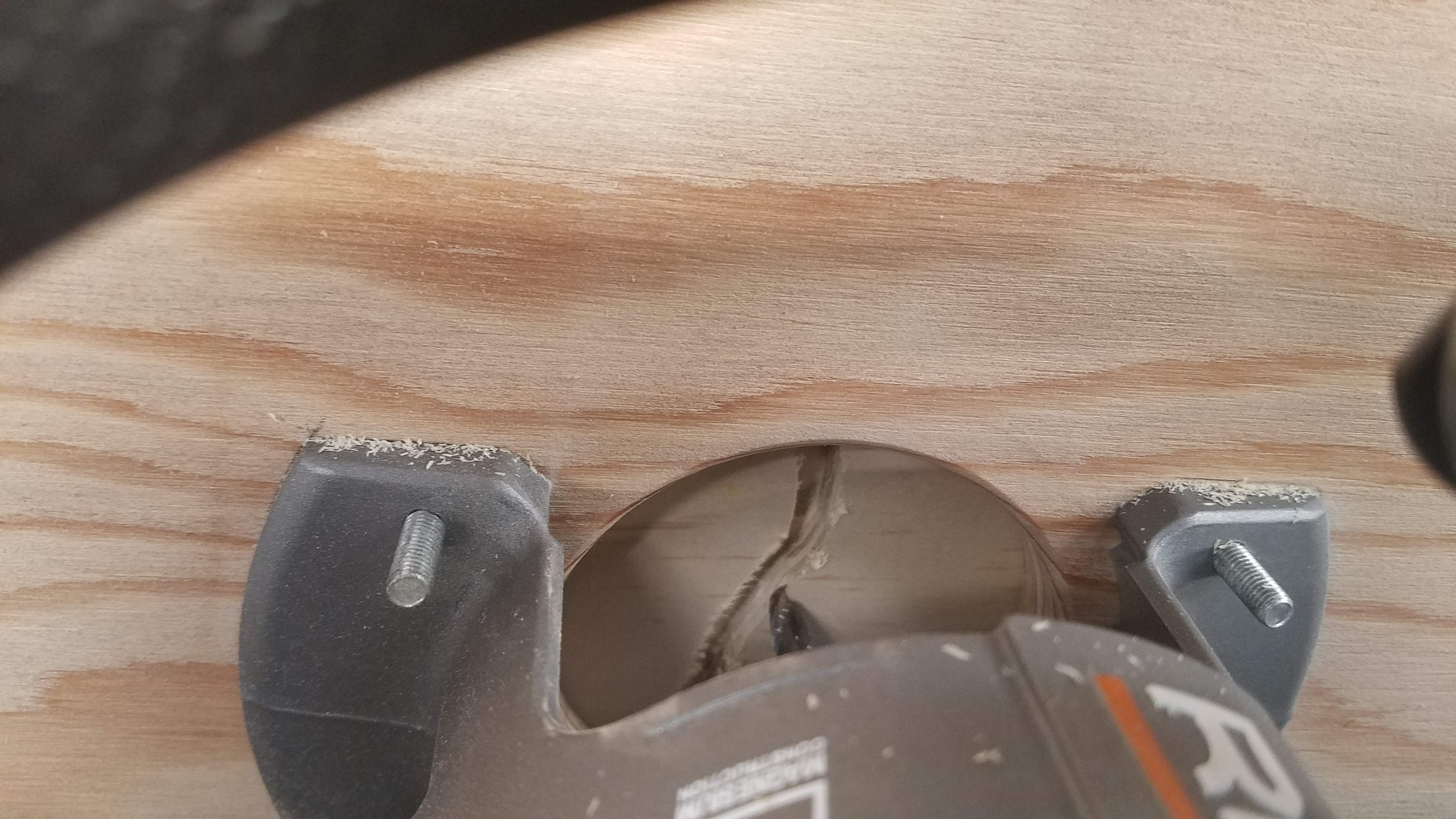
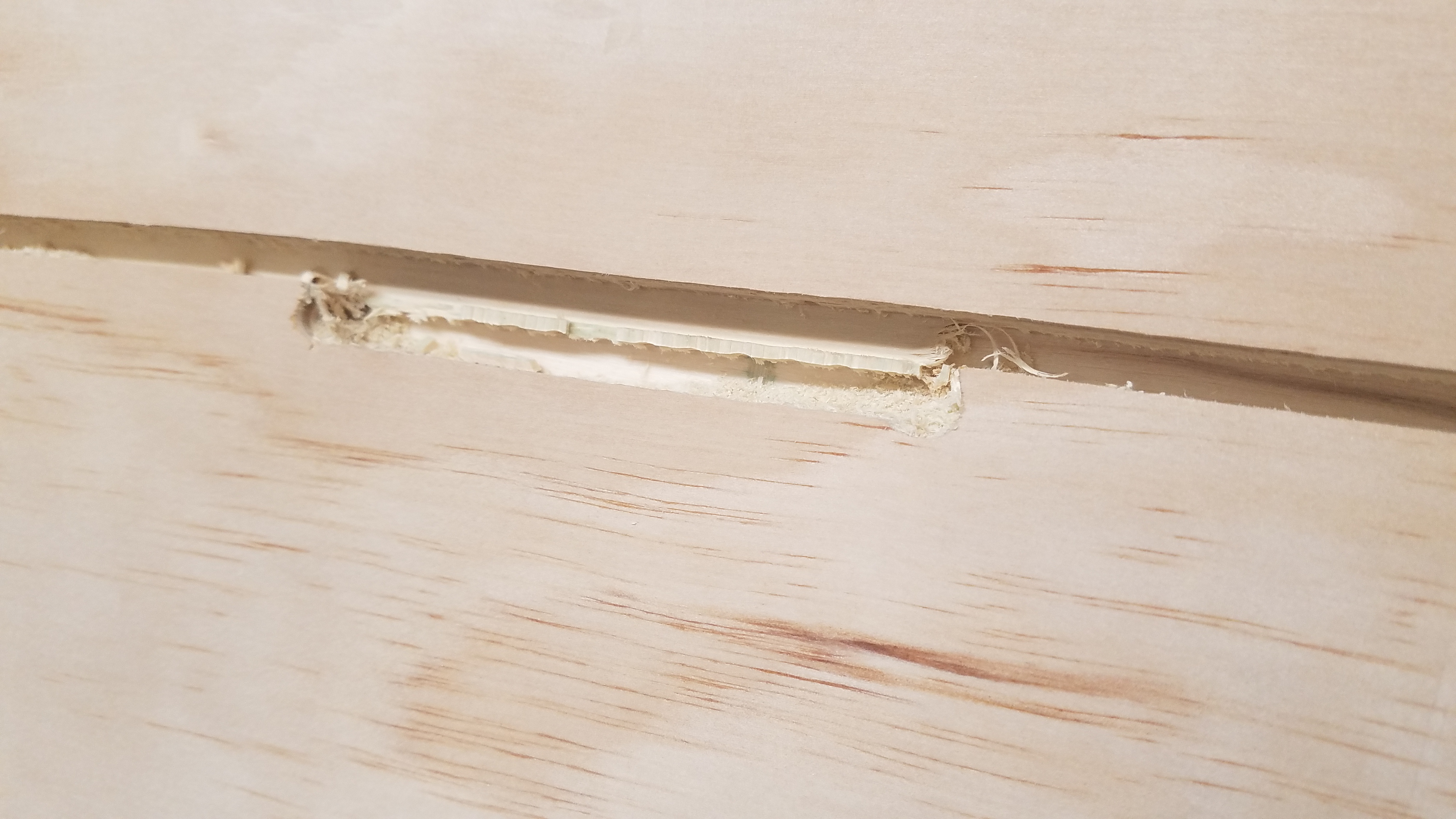
The 3 passes went well. Then something happened in the upper part of the contour (see picture). The bit started moving down.
I stopped the job, went back to center and restarted the job. Once back, the beginning of the cut did not align with the first passes. Like if the whole thing has moved, like if the chain or sprocket skipped.
Any idea? Can I save this cut?
I was able to get it back into position. I started to cut again and after a good pass is started biting into the path again
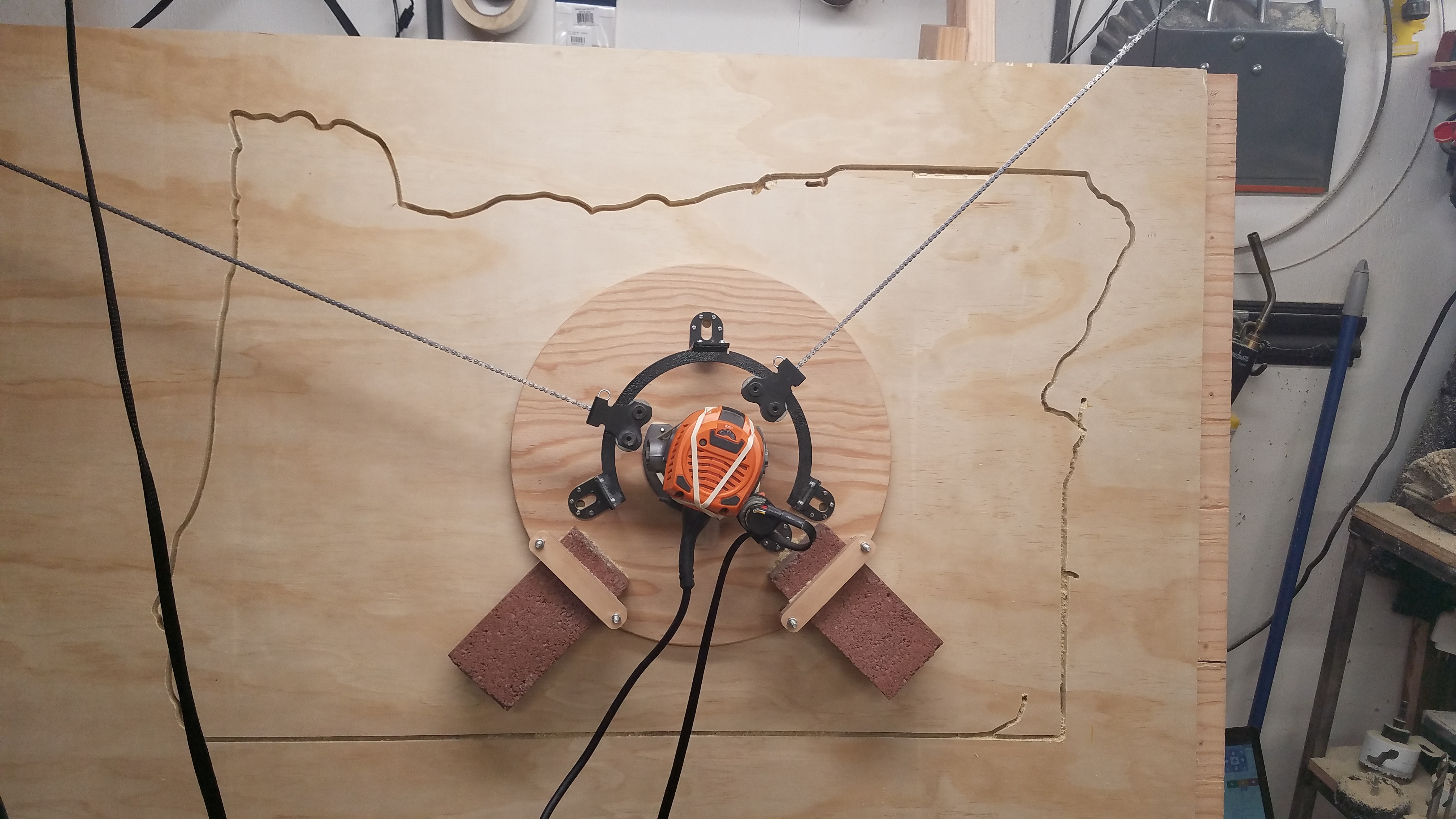
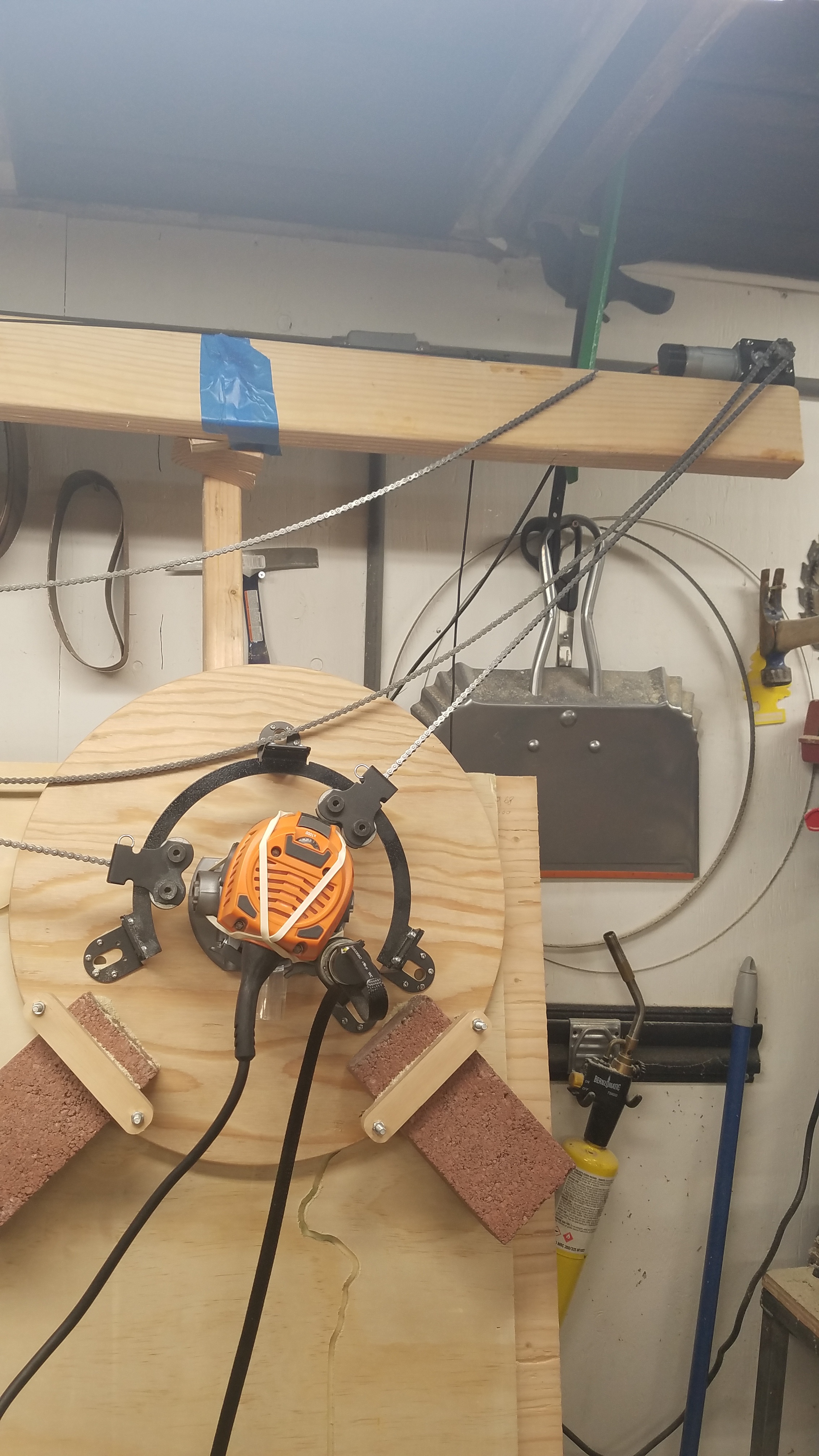
The chain is parallel to the workspace. I checked that when I built the sled. As for the slag, I am using the bold on frame. Any suggestion about how to keep that parallel?
I am attaching a picture of the right top of my frame setup.
So basically I need to keep the router as slow as I can? As for the cam, is 1000mm/min a good speed? (it should be maslow maximum speed).
you don’t want to have that little tension on the slack side, but with the
standard stretchy cord you don’t have much tension. you can try doubling up the
strechy cord, or replace it with a weight.
it also looks as if you may be having trouble with your sled sticking, can you make a video of it cutting? that may help us figure out where it’s going wrong.