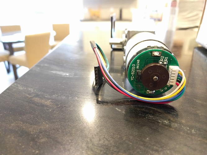
For those that were not part of the Kickstarter: Where to obtain the main motor/worm gear/encoder

Looking at the Bosch windscreen wiper pdf, it would be nice to have those kinds of performance curves, specially when people start experiments with different gear ratio’s

Also note how Bosch notes about the measurements being made at 0 Ohm wire resistance.
(in other words with no wire at all)

Does anyone know the Internal resistance of the motors. And the wire resistance of the cables that are being used on the maslow?

Just to get an idea how much loss there would be in then ideal situations, and could be in optimal situations. Since the wires are pretty long i would guess that there is a decent amount of influence at play.

1 Like

If anyone has access to the Bosch-automotive database that could help
www.bosch-automotive.com maybe someone knows how to climb trough a digital window? :slight_smile: Or eventually a reseller website with spec specific searchable database. (Anyone with a job in the automotive industry?)

I ordered one of the A58SW-555B motors that @Gero and @S1lver mentioned to try and create an improvement for the machine. It will take a month or more to arrive, but I will let you all know how it works.

3 Likes

My 24V/1:212 motors with 11PPR arrived yesterday. I hope to get them mounted tomorrow and see if they work better than my 1000PPR encoder at the shaft.

Anybody looking for a higher current output board SainSmart has them for a good price, maybe a Black Friday sale item.

2 Likes

Was to cold to get any real results. The motors are plenty powerful enough to use but the encoders where not picked up the the “test motors” routine. Tried to update GroundControl but was freezing by then and went inside. Need to find a propane heater…

2 Likes

I just want to let everyone know that we’re going to have the official motors for sale soon! We were able to order some extra with the last batch of machines. There are some software issues I need to take care of which are the top priority (and thanksgiving is this week) but hopefully we will have them up soon

6 Likes

How soon can kits be sent out if we sign up today?

I’m interested in these motors (+ 1 Arduino shield)
Is it only the wormgear motors or also the Z-motor?

All in good time… No rush, no pressure.

I just wanted to keep everyone updated that when I contacted the order fulfillment service that we use about adding the motors to their stock I was told that they are going out of business effective Thursday and that not only would they not take the motors, but that I have to take all the other parts back by then :roll_eyes:

We’ll find someone else, or just take over all the order fulfillment ourselves, but there’s going to be a couple days delay while we figure it out

3 Likes

Lucky you asked, your stuff could have become hard to get to. Life’s a whirl, isn’t it?

2 Likes

Oh bummer! Nothing like a fire drill to get the blood pumping, eh?

Any word on an “official” replacement motor?

Alright the A58SW-555B servo arrived. So 23 days total delivery time, not bad.

This morning is beer brewing, so no opportunity to test it now, but I should be able to tinker with it this week and will provide more details.

IMG_20171202_112819IMG_20171202_112858

4 Likes

@thuber , with your small motors, did you have to modify any of the code? Or did they just wire up the same and work?

Dfsrobots,
They were direct replacements. Just be sure to get the wires right for the connection. I was messing up in the beginning by having the motor signal on the wrong lines. If using the real maslow board, you will need to come up with solution for cables. The one that comes with tiny motors are tiny, lol. I made cables, which also keep the encoder lines away from the motor power lines. I just did that to help in any way the signal, because it has over 14,000 pulses per revolution.

Now with Bar releasing some of the motors for sale, you will be able to go that way.

Over and out…
Oh, I threw together a linkage system and wow, talk about a difference. Although, I really want to get the circle set up once available.

2 Likes

We’ve got the motors available! We’re dropping them off at the new fulfillment center right now so they probably won’t ship until Monday, but they are available from our store at http://www.maslowcnc.com/store/

We tried to keep the cost down and each one ships with the wire to connect it to shield because that can be a hassle to make.

I’m glad we can finally sell them, sorry it took us so long!

3 Likes

WINNER! Thank you Hannah and Bar, I’m on the store now. Really appreciate you sorting this out despite the logistical issues with which you’ve recently been encumbered. Looks like 2018 is going to be a big Maslow year ;¬)

Enjoy the festive season and wishing you a joyful new year.

Miles

2 Likes

I sourced these motors https://www.aliexpress.com/item/Precision-GW4058-31ZY-Turbine-Worm-DC-gear-motor-Magnetic-Bipolar-hall-encoder-Dual-output-shaft-motor/32798101510.html with a 1:280 ratio. The specs are here for the 12V:


Everything seems to be okay with these, but as mentioned above by people more knowledgeable than I, the stall current is a problem.

This will explain why I’ve not managed to get them working with the Maslow H-Bridge shield. My wiring harness wasn’t very attractive, and may need another look, but I’m pretty sure the wiring isn’t the issue.
Is there a quick fix to the stall amperage, such as throwing in a resistor or such like, or am I dreaming? I think the latter! I may buy another H-Bridge to get these motors up and running in the future, but I currently await the proper motors as I’m tired of failure this week!

A question, if I may, to those more knowledgeable than I:
Am I likely to have caused my Maslow H-Bridge damage by trying to get it to run these motors? I never managed to get any motion when attempting test runs.

Thanks in advance.
Miles

Those motors should work because (unless told different) the 2.3 amp stall is ok on stock controller. That is if I read that correctly.

The reason they did not work (if you just plugged them in) THE ENCODER WIRING IS DIFFERENT. I could not see the entire ad that showed the wiring layout but the part I saw was wrong!

I will post the correct pinout for you in a minute when home to double check. I know for a fact the board is set up different. This is why you got zero movement. Easy fix. Check back in 30 mins!
Regard,
Todd

Ok. Here is the deal. According to the datasheet on the power SO chips used in the stock board:
Non repetitive max 3.0amps
Repetitive (80 on 20 off) 2.5 amps
Dc operation 2.0 amps
But later in the datasheet they mention the technique to add current capability. Parallel use of chip (adding second in parallel will increase amperage) but the main section list the values i gave you. Plus each states per channel. Which is why they list max at 4 amps under chip description.

Either way I think you are good to go, especially if just using 2 motors, one on each chip for now.

Your hookup. This was where I messed up because I only have 10 min time slots to do this stuff and casually looked at the functional placement schematic when making cables and switched the dc power with the ppr lines, doh. After Bar showed me that the schematic was not wrong but if use to reading how I did and not tracing (my fault), you would get them mixed up.

So, if going off the partial picture I saw of the encoder wiring for yours you can see it is not the same as the board.

So the great part is that all cables that have connections like these that I have seen, are easy to rearrange. Just use a pin or tool to push on the showing metal and lift the plastic gently right behind it as you pull out the wire. Then put back in the correct ones and they will snap. Hopefully having voltage on the encoder meant for the motor did not fry encoder but I do doubt it. If so tell me cause I was able to replace a hall sensor no problem…but can get touchy.

The pinout for your board (Maslow) is as follows:

From the top looking down and power plug to the right:

1.m
2.m
3.g. note 3 and 4 might be switched (Not in front of me to verfy)
4.3.3-5v
5.en in
6.en in

BUT I KNOW FOR A FACT THAT BOTH MOTOR PINS ARE AT THE TOP OF THE FEMALE PLUG ON BOARD.
BOTH OF THE ENCODERS ARE ON THE 2 BOTTOM PINS AND THE GROUND AND V FOR ENCODERS ARE IN THE MIDDLE.

If you have any questions, feel free to ask. I do not see why you could not get them set up with what you have assuming these are 2.4 amp peak motors…if higher than that…no, but you can get a cheap 5-7 amp board no problem.

Best of luck.
If you need the actual mapping just ask, I am not in front of them and would need to see your encoder. My brain is scrambled a bit so not remembering specific plus and minus. But fact is the pinout I gave is correct. Actually back when I first set it up and was shown my error, many others chimed in and said they would have done the same thing i did based on the posted schematic (Not placement schematic …but initially read it as one)

Regards,
Todd