G-Code generated via VisualCAMc App/Plugin for OnShape

I spent a good bit of time watching youtube videos in an attempt to figure out VisualCAMc…long story short it works, its not perfect, and if you mess up in process your basically have to start over…I am going to attach quite a few screen shots with explanation of what steps worked for me…just like all CAD, the more you do it, the easier it gets.


Above is a sample that I made with OnShape, note that there are 6 Parts.
So from hear if you do not have VisualCAMc loaded go to the App Store and get it.


Just go to the CAM section and scroll down to you see VisualCAMc


Once you have the App and your part is complete, go down the plus sign, click it and then go to Add Application


In the above picture, you will see that every element became a part, well to fix this we need to go back to OnShape and boolean the parts


Just select everything and then hit the boolean icon


note that there is one part now
Then Load VisualCAMc app


select your part and hit add (see below)

Now this is were the fun begins…you have to visualCAMc what you want to do, but first we have to set up a few things.

Basic task that must be done before we start:
Set up machine (I used the default 3axis)
Set up Post (This is basically your CNC)
Set up Tools
Set up Stock
Set up Work Zero
Then set up actions to process


Set up the Machine (3axis)


Set up the Post (I chose X-Carve because I saw a post some place that MaslowCNC used GRBL in some form, and it worked)


You have to setup Stock, this is basically given the machine an idea what material it has to remove

2018-05-07%2017_41_43-Maslow%20Example%20_%20VisualCAMc
From trial and error, and one obscure YouTube video I have determined that you want to check Bottom SW under the Position.
Then you want to click the Copy Model Bounding Box (not sure why, but you don’t you will be repeating the above processes because the steps after require it.
Then hit Save

2018-05-07%2017_45_20-Maslow%20Example%20_%20VisualCAMc
Next hit select the Work Zero Icon on the task bar


On this screen under TYPE, you want to select Set to Stock Box
Under Face, Select Highest Z
Under Position Select SW
Then hit save


Now, we have to give the machine some task to do…so from this point you need to think from center out on your project.
Since I have some receased circles, a rectangle, and some lettering, we need to select them…I found that either mouse button will work for windows…one youtube video suggested that the right works better…
From the Top of your work piece move your cursor to the item you want to select, note it turns red, click it and it will turn green…this is tedious, but you have more control now

Once everything is selected click the 2 1/2 Axis icon


Now select the Pocketing Icon


First thing to do is select tool, then click on the add tool icon


Here you can select what kind of endmill your are working with…I just changed this to Flat Mill
I also changed the tool diameter to 0.25
Then hit Save

Next we have to set up some Machine info
I didn’t take a picture of the preset values, but they all need to be changed.
MaslowCNC runs at 800mm/min which comes out to be about 31.49inches/min (I rounded down to 30
I selected CW, but in the end, it mills CW and CCW (I haven’t found a way to stop this)
I didn’t change the spindle speed


We need to tell the MaslowCNC to pick its endmill up while its moving
I chose Stock Max Z + 0.25"
Automatic works too

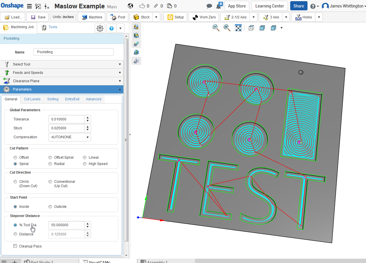
Now click the Parameters Section


This is the section that everyone is looking for!
I changed the cut patteron to Spiral, however you can run a test run and watch the end mill travel around your part to decide which you like
Since we are working on the interior part of our project, click the inside options
The next section is important…this tell the MaslowCNC how much to move over of the next cut…25% of 0.25EndMill is 0.0625inches…I have increased this to 40 and 50%…30 and 40% work better in my opinion

Now after you finish this, select the Cut Levels Tab at the top of this section


Click the At Top for Geometry

Next you have to tell Maslow how deep to cut, since my stock was 1inch and my cuts are 0.25…once you fill this in, it will add that value to everything…change the Rough Depth/Cut to 0.15 (this about 3.8mm per pass)

I select the use 3d Model to detect depth…not sure if this works for MaslowCNC, but it doesn’t cause any problems

Then Depth First


I didn’t mess with much here
just selected Path

Now, lets see if what we did works…select Generate Toolpath


I started not to include this picture, but as you can see the toolpath doesn’t follow all the letters…basically, you have to delete this whole process, go back to OnShape, fix the item and start the steps all over


Corrected model and with new toolpath…and I increased my step over distance percent on this one
2018-05-07%2019_09_29-Maslow%20Example%20_%20VisualCAMc

2018-05-07%2019_10_19-Maslow%20Example%20_%20VisualCAMc
85% here

To get back to basic setup, click the Isometric icon on the tool bar


Now, for the next step, we have to un-select everything we selected for the pocking step…


The above picture is of Isometric view and note that nothing is selected in green at this time…I am about click the outside of the part so we can cut it out.


Once selected clock on the Profiling Icon under the 2 1/2 axis icon

You will have to set the Tool, Feed and Speeds, and Clearance just as you did for the pocket operation


Under Parameters:
Cut Start Side:
Right or Left is ok
But you need to check the box Use Outside/Inside for Closed Curves
Then select outside


Under Cut Levels
Select At Top
Then enter your material depth
Then under Rough/Depth/Cut enter 0.15
Depth First

Then the last thing I do, it go to Advanced
under the Bridges/Tabs select what you would like here
I chose rectangle


Then click Generate


note the Tab on the profile of the part just below and between the E and S


you can simulate your cut if you like

Now we want to make our part…
Click the Pocketing icon first…then hold down the shift key and click on Profiling Operation, both will highlight…(I can’t remember, but I don’t think I clicked the Work Zero or not)
Then select right click and select Post Process


G-Code is ready for download

This worked for me…please pay attention to the travel speeds…
James

3 Likes

Wow great tutorial. One question I can’t find an answer to is if there will still be a free version after beta ends. Do you know?

1 Like

I don’t know the answer to that,

Freecad has already a CAM built in you could try that as well. If you like to design in onshape you can take your 3D file like iges or igs, step, stl, etc to freecad just for the CAM portion.

This means you could still design in onshape and move to freecad for the CAM.

Just a suggestion… BTW Onshape does not have the full blown parametric, assembly, NURBS, surface, Simulation, FEA, Architeture, CAM… functionality of Freecad.

and it is free

you need to take another look at onshape.

It is a full blown parametric CAD system with no cost (but not open source)

the various other features you mention are all available as plugins (usually
with multiple options available, not all at no cost)

I actually used OnShape for a little while. I do not like that it does not have any way to configure it’s code, you cannot do your own macros… Plugins are not the best… Especially for CAM…

It is a tool for some engineering applications and certainly will not crash and not with obvious bugs as Freecad. However, it breaks away with some CAD traditions…

As for being a Full blown parametric CAD… I disagree, I think for Maslow applications it is ok… I would never use it for my engineering job, not any engineer I work with me or under me.

Going back to the topic of this thread, I think you could still use Onshape for your design if APP/Plugin visual CAM seems to have functionality… I’ll give it a try, but for good CAM you should move out of Onshape ASAP.

2 Likes

I actually used OnShape for a little while.

how long ago?

I do not like that it does not have any way to configure it’s code, you cannot
do your own macros…

can’t do your own macros? you can do feature scripts that do a lot of rather
powerful stuff. People have implmented belts/chains/dogbones and a lot more in
them

Plugins are not the best… Especially for CAM…

why not?

a plugin that is put together by someone focusing on one thing can be better
than a ‘built-in’ that’s done by someone without expertise in the area.

why should you have to change your CAM if you change your CAD? why should you
not be able to use the best CAM software and the best CAD software

It is a tool for some engineering applications and certainly will not crash
and not with obvious bugs as Freecad.
However, it breaks away with some CAD
traditions…

and that’s a bad thing? :wink:

seriously, it may be bad for some things, but in others (like the ability to
have multiple people viewing and editing a document at the same time) it’s
progress.

A lot of “CAD traditions” are a legacy of CAD programs being many thousands of
dollars, running on workstations that were equally expensive, so the cheap part
of the process was the labor of the CAD operator. That leads to bad solutions
when the costs of the hardware and software come down.

As for being a Full blown parametric CAD… I disagree,

why? what is it that you can’t set a parameter to?

I think for Maslow applications it is ok… I would never use it for my
engineering job, not any engineer I work with me or under me.

that’s your choice, and it’s a valid choice, but it’s not the only choice (there
are companies using it for their engineering departments)

Going back to the topic of this thread, I think you could still use Onshape
for your design if APP/Plugin visual CAM seems to have functionality… I’ll
give it a try, but for good CAM you should move out of Onshape ASAP.

What CAM program do you consider best?

onshape has the ability to use many cam plugins

CamWorks
Kiri:Mota (free)
Oncreate3D (free beta)
Mastercam (2017 and 2018)
Prospector
Esprit
VisualCAM (free beta)
SprutCam

why are none of these (including the expensive commercial ones) any good?

You have valid points and respect your opinion.

That being said, I need to correct your ignorance on the status quo of design with correct tools.

I work for a major corporation that designs and manufacturers phones and consumer electronics here in the Silicon Valley. I do not agree with the “expensive workstations” because where I work most engineers use computers less than 1000 dollars. We run Solidworks and Pro-E (CREO) in laptops under 1000 dollars.

There is no “CAD operator”, we have engineers. industrial Design… Product engineers, development engineers, testing eng, etc…

Our entry level engineers make somewhere $100kto$120k so I would say the expensive part is always find the bright minded people that can design our products. Actually the industrial design people make over 200k/year just FYI.

Your statement:

is not accurate. It is wrong to put it mildly.

The design come from Industrial design team and we use master model technique. In OnShape you could work in master model but it is clumsy at the best. I did use OnShape recently when I looked at the Maslow the first time.

And about your comment on parametric modeling, actually onshape is try to change things based on their agenda.
Please educate yourself first

Since this post is way out of topic, this is my last post on this topic.

I know dlang is very knowleageable on the Maslow I want to keep friendly tone so I can get help with my maslow if trouble arises.

Again, I do respect your opinion and OnShape is great tool for Maslow.
with all this said, I still think Freecad is a more traditional approach that could benefit the maslow communitiy since it already has a CAM built in.

1 Like

David was saying that in the past hardware and software was very expensive, and the designers were comparatively cheap, and this legacy (i.e. actions from the past) has carried on in some products and traditions. Why optimize the cheapest part? Today that situation has reversed, people are more expensive than hardware and software.

He’s right. For example, when I worked in the 70s graphics workstations were 50 grand and up (often way up), experienced engineers thought $20K was exceedingly big bucks; I started at half of that. Otoh, a decent car was $3K and my 73 Lotus cost $5K in 1975.

I work for a major corporation that designs and manufacturers phones and
consumer electronics here in the Silicon Valley. I do not agree with the
“expensive workstations” because where I work most engineers use computers
less than 1000 dollars. We run Solidworks and Pro-E (CREO) in laptops under
1000 dollars.

There is no “CAD operator”, we have engineers. industrial Design… Product
engineers, development engineers, testing eng, etc…

Our entry level engineers make somewhere $100kto$120k so I would say the
expensive part is always find the bright minded people that can design our
products. Actually the industrial design people make over 200k/year just FYI.

Your statement:

is not accurate. It is wrong to put it mildly.

This is correct today, but the “CAD traditions” were created in the 1980s and
1990s years ago when CAD workstations were >$5K (in 1990 dollars, roughly double
that in 2018 dollars), and CAD packages were >$10K/seat. At that time there were
CAD operators doing the CAD work, not the engineers.

This has changed, today the workstations are around 1/10 what they used to cost,
and the CAD software is << 1/10 the old cost (down to free, depending on what
features you need), meanwhile, as you say, more high priced engineers are using
CAD directly (although there is still the category of “Draftsman” in at least
some fields who replace the old CAD operator) and the result is able to render
things in real time as opposed to being limited to wireframe diagrams and
rendering being overnight jobs.

I stand by my position that just because it’s a CAD tradition, it doesn’t mean
it’s good. The traditions were formed in a very different environment.

The design come from Industrial design team and we use master model technique.
In OnShape you could work in master model but it is clumsy at the best. I did
use OnShape recently when I looked at the Maslow the first time.

And about your comment on parametric modeling, actually onshape is try to change things based on their agenda.
Please educate yourself first
Introducing Parametric Modeling 2.0

that’s not saying that they don’t support parametric modeling, but that they’re
introducing features that they consider an improvement.

what I see in that video is improvements to make the engineers life easier, you
can still do things the old way

Since this post is way out of topic, this is my last post on this topic.

I know dlang is very knowleageable on the Maslow I want to keep friendly tone so I can get help with my maslow if trouble arises.

I help the people I argue with (If I didn’t, I wouldn’t help many people :slight_smile: )

Again, I do respect your opinion and OnShape is great tool for Maslow.

with all this said, I still think Freecad is a more traditional approach that
could benefit the maslow communitiy since it already has a CAM built in.

I’m not at all arguing against using Freecad. I’m arguing against what seem to
be faulty arguments for why you should switch to freecad.

Given that many people are using inkscape/makercam (and exporting from freecad,
onshape, fusion 360, etc to get an svg to load into inkscape), your objections
to the options in onshape as (paraphased) “not being real cad/cam” is not
reasonable.

saying that ‘plugins are bad’ is not a valid technical argument. Saying that
plugin X is not as good as build-in cam Y because Z is a very valid argument.

There is a lot of stuff here that I don’t know. When I press for details, I’m
actually interested in hearing the answers. It’s not a matter of trying to shut
anybody up.

1 Like

I bet you want me to reply. But I won’t…
I know how to walk out of this type of situations.

Live long and prosper my friend.

agree