I hope red=hot and black=ground (they’re the edge wires on the harness)…? I’ll just splice into them and wire directly into the 5v on the board.
Micro center trip got pushed to Monday. I’ll plan on executing this early next week.
I hope red=hot and black=ground (they’re the edge wires on the harness)…? I’ll just splice into them and wire directly into the 5v on the board.
Micro center trip got pushed to Monday. I’ll plan on executing this early next week.
I have a couple of these guys that might work…
https://www.dfrobot.com/product-1616.html
Okay, this may be a bit simplistic (no added electronics or metal plate, etc.) But I stumbled upon an easy way to get an accurate zero. After changing out my bit, I get it close by eye using the z-axis controls and save, then turn on the router. I then lower it down an additional few mm then raise it high enough to move the sled out of the way. Using a depth mic, I compare how much I told the router to plunge from zero to how much it actually plunged and adjust zero accordingly; accuracy should then be within a fraction of a mm. I don’t have much of a drift problem in my z axis (I’m using a meticulous z-axis sled) but I’m sure this method would work to correct drift periodically also.
It’s alive! I spent a couples days prototyping different placement and techniques.
tl;dr: it works even better than I hoped. Total cost was ~$35.
I ended up screwing the VL6180 sensor on the bottom of the bracket which holds the Z-motor. Then, I super glued a piece of white glossy plastic (cut out from a blank white electrical face-plate) to the “trigger” on the Rigid (the clasp you pull out to release the Z-axis so the router can be removed). Both planes (sensor & target) are thus solidly attached. The glossy white plastic provides a very good target for the TOF sensor (highly reflective).
Right now, the sensor data just goes through an Arduino Nano before being fed into the Raspberry Pi controller. The data is read by Node RED via serial (USB), smoothed, and then piped into a Home Assistant sensor. No fancy automations yet. When I change bits, I just push the router in to touch the bit to the stock as I am replacing the router and take note of the mm reading from the sensor. This is much quicker than manually zeroing, and requires no extra hardware (touchplate). Then, any time I need to re-zero, I can move the Z until the sensor reads the same original value and then “save Z.” This can even be done remotely.
I suspect the easiest way to automate this would be to simply implement a touch probe. I believe it’s just a matter of closing the circuit on AUX4 when the sensor reaches the original value…
But I wish I could just tell Maslow / Web Control what the actual distance is, without moving/probing the Z axis at all. For example, I wish I could send a command to Web Control that says “the current Z value is actually +3mm” and have it set the zero value based upon this information. @madgrizzle any thoughts on this? I’m happy to implement it, but would appreciate any tips or words of caution if I’m totally off the rails here.
Not 100% sure, but the G10 Zxxx gcode can be sent to set Z to whatever value. Define Z-zero button just sends G10 Z0. So send G10 Z3 (make sure your in metric mode) and I think it will set the Z-axis height to 3 mm. There’s an off chance that it will set the encoder steps value to 3 (which is really, really small height) but give it a shot and let me know.
edit that worked. I was briefly thrown off by the fact that there are Units and UnitsZ. Despite the name, it appears that Units are what matters when setting the depth via the G10 Z command. If you have the Z modal open and set to MM, but the “main” units are Inches, then G10 will assume you mean Inches.
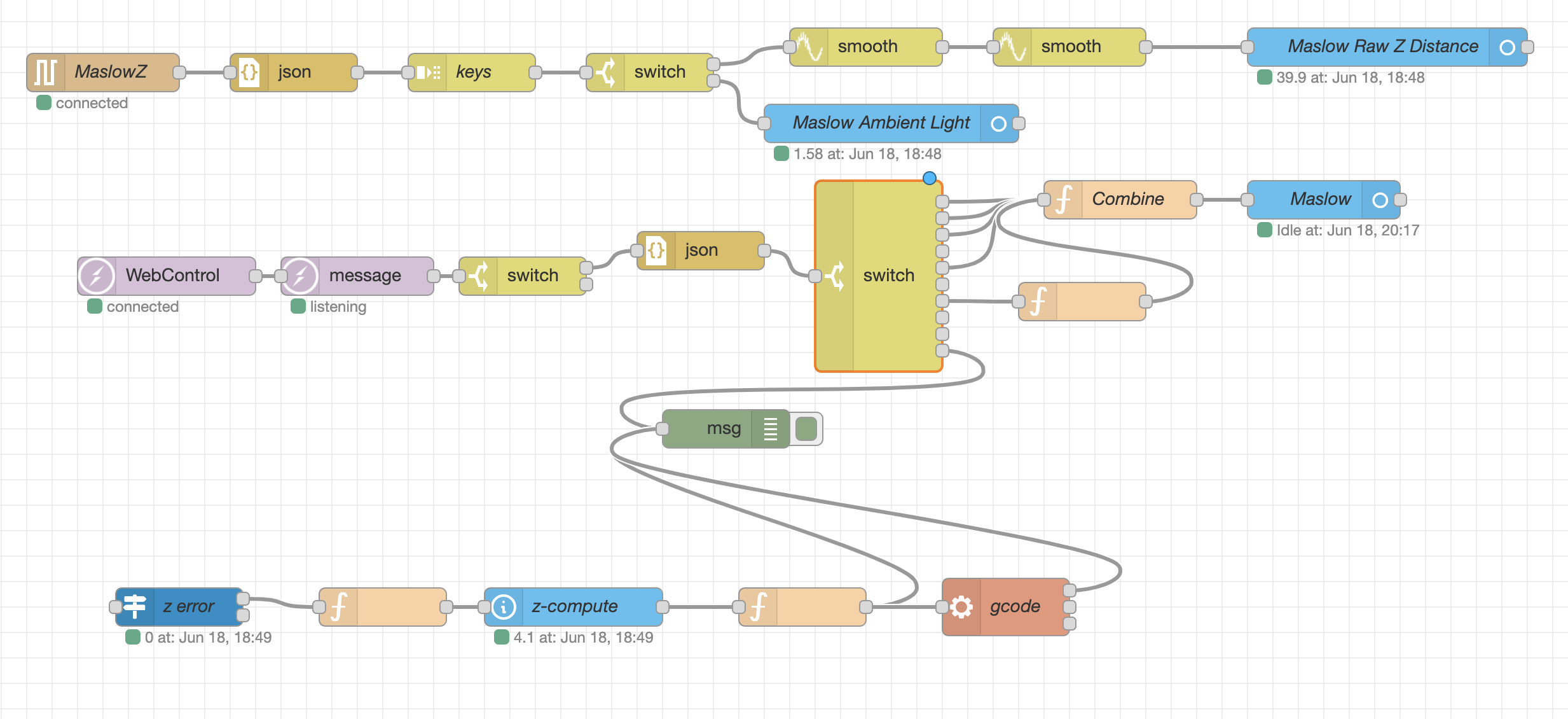
I’ve now also hooked into the SocketIO interface from WebControl with Node RED and Home Assistant. This is what lets me detect the Maslow’s position, and compute the correct position and send the gcode.
I’m going to work on improving accuracy even further and let it run during some test cuts…
Possibly [very] unpopular, but I find wood is never flat and my frame will skew up to 1mm in any direction. I commend your vision Sir, but I think it may be trying to fix an unfixable problem…
(I’ll just run away now)
Bowing/warping is a fact as old as wood itself. Whenever I go to home depot I always see people trying to find the flattest pieces. I correct for the bowing with a heavy sled and strategically placed screws into the backboard. When done well, I cannot detect any variation.
That looks fantastic! Nice build.
What is that flow based program you are using where all the boxes connect together?
Thanks, @bar!
For test cut #1, I did not use any auto-correction. I just monitored the Z Computed Error manually. I’m smoothing the values to get rid of noise, but this causes lag. I’m getting ~0.5mm accuracy while Z is stationary, and ~.5mm while the Z is moving (due to lag). I think the better approach will be to reduce noise from the input signal, which is to say: darken the area between the sensor and its target (LIDAR works better without correcting for interference).
That’s Node Red. Each “node” is coded with Node.js (Javascript). But most nodes you can just find and install as packages. Super easy to prototype stuff around the house. I’m using the following nodes:
The rest are all built in nodes and some minor transformations. Home Assistant is mostly just for visuals.
So now that you have a dedicated Z axis are you still using this electronic method? for $35 one can make their own meticulous z axis, so I’m curious to see which solution you prefer? The electronic or mechanical?
I’m now just using the mechanical method ![]() Ironically, it was the splice of the Z-axis wire that probably caused the failure of my shield… the black wire solder joint became loose after (dis)connecting the Z-axis many times while testing my firmware upgrades.
Ironically, it was the splice of the Z-axis wire that probably caused the failure of my shield… the black wire solder joint became loose after (dis)connecting the Z-axis many times while testing my firmware upgrades.
I actually plan to use the Arduino mounted on top of the sled to control a small servo to change the RPMs on the router, eventually. Unless there’s a way I can splice into the electronics of the router and do it via a volt stepper…
from what I have read and from the prices I’ve gotten it’s cheaper to just get a 800w spindle if you want speed control . there are aftermarket solutions like thsi $155 speed controller but they do not economically make sense
I wasn’t planning on looking in to this for a while still, but do you have any info about how I would connect the spindle to the Rigid’s RPM knob? Or is that unsolved?
I also want to 3d print a second spindle holder that can fit my spare laser, so I could swap in a laser by swapping out the Rigid router from the metal bracket…
I meant a spindle to totally replace the router like this.
People have opened up the ridgid which has its own controller inside and a Pot, but turning the pot down does not allow it to slow down any more. there is a thread somewhere on here.
For what It’s worth, here is what I use to zero in my Z axis. It’s simple and effective.

Good Info. I might steal that idea.
Wouldn’t a z-axis probe be even easier? You avoid the battery, LED, resistor, and case. AFAIK, you more or less just wire the copper plate directly to AUX4 on the original Maslow. And then enable the z-probe in WebControl or CNCjs, and it does everything automatically, so you don’t have to manually watch for the light. Same principle: the circuit is completed, but the Arduino receives the signal and sets the new zero location.
Yes, this is exactly what I did. Super easy to do.
Get the bit close to the touch plate and hit the touch zero button. It will slowly lower, stop when the circuit is complete, and save zero.
I find you suggestion for auto zero intriguing . I do use two different bits, of different lengths so there would be a need to calibrate the probe to the bit height at each changing. So I feel that would just be back to the original problem but still doable. I’m not sure measuring the probe instead of the actual bit height is best practice as if the probe is not accurate (lots of vibration on the sled) it might be plywood abuse. But then I try to remember the three words that all knowledge is built on ; “I don’t know”. I would be careful and isolate the probe (if you use the probe to touch the electric switch plate) as I’m guessing the router case is grounded and probably shares a common ground with the computer and/or maslow and taking the voltage for the probe from the DC power may release the magic smoke somewhere. You could always decrease the current to a safe level with a 1K resistor and it would still bring the input high (if logic high is used on aux4). Additionally if not isolated the case may prevent the voltage from triggering the Aux4 probe input as the case would just tie it to ground. Please post progress on this as I would like to see the outcome. Jon